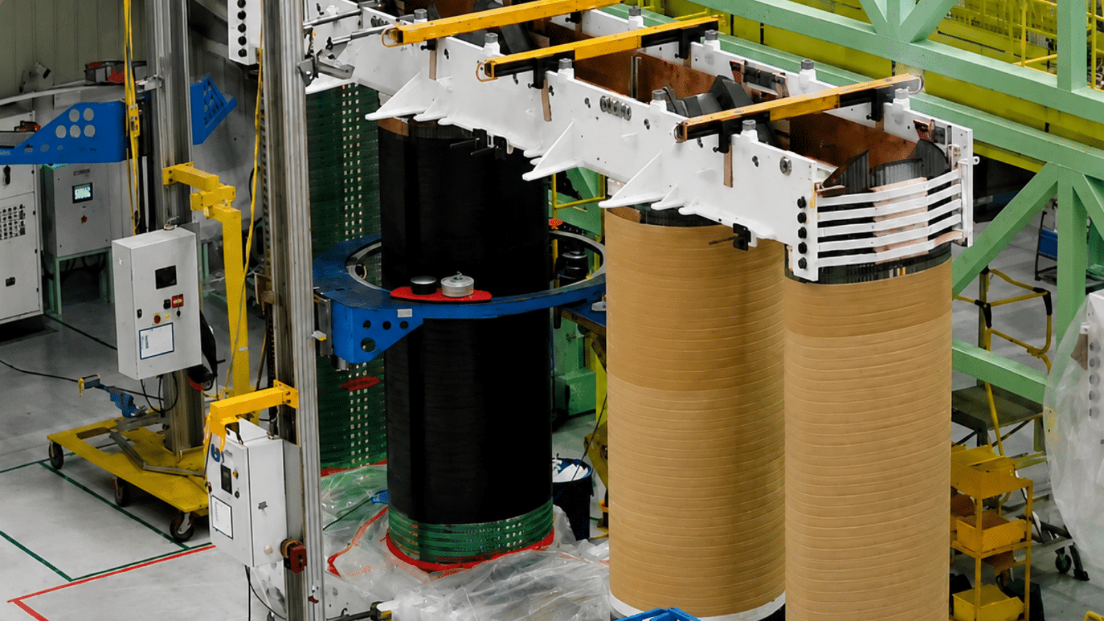
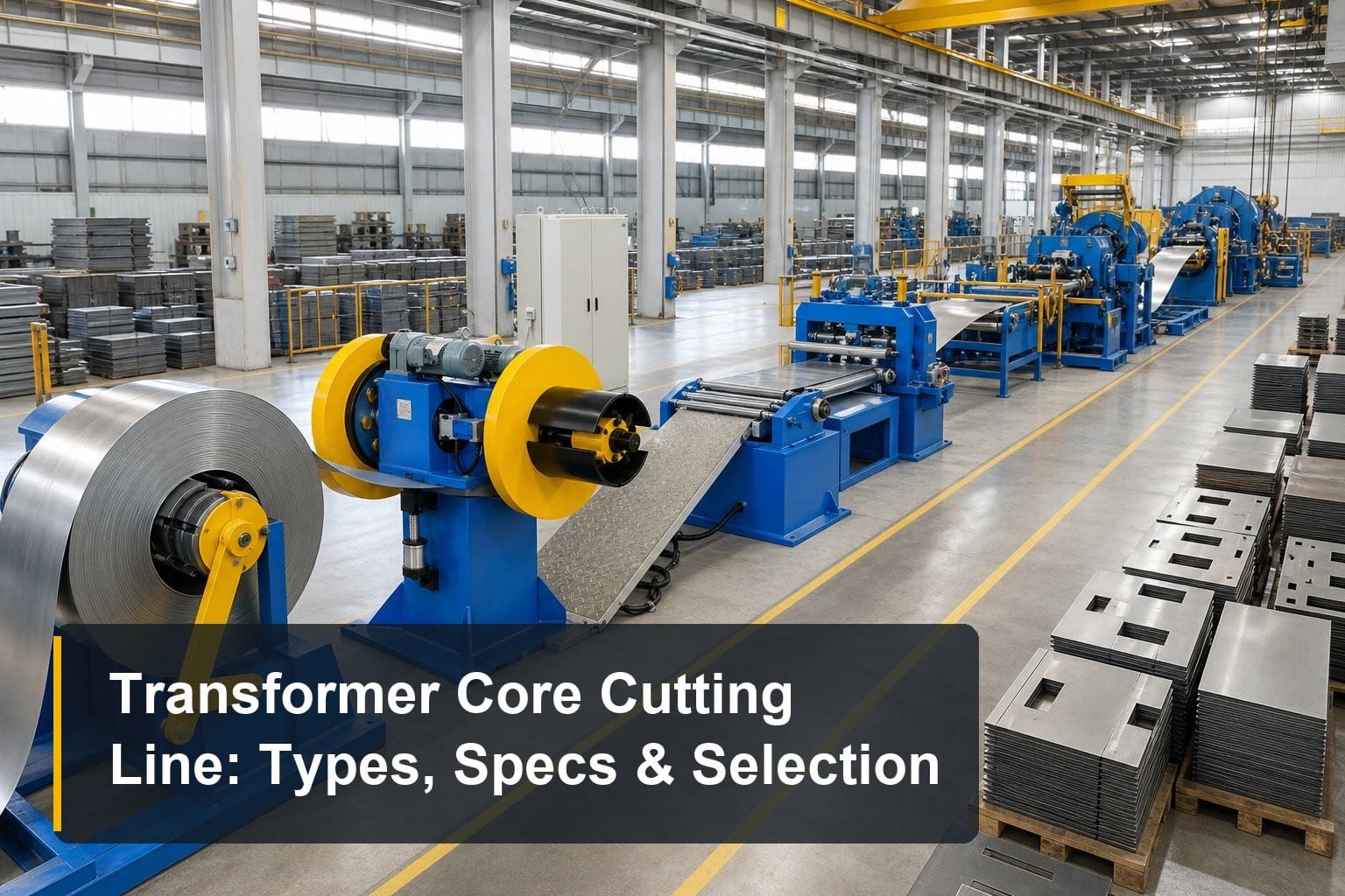
TL;DR: A transformer core cutting line turns CRGO silicon steel strips into finished core laminations at up to 240 m/min, with cutting length accuracy of ±0.1 mm, angle accuracy of ±0.025°, and burr ≤0.02 mm. Five main configurations exist — center positioning, servo sorting, large-transformer heavy duty, side positioning, and center piece lines — and the right choice depends on your coil width, production volume, workshop layout, and labor strategy. This guide covers how these lines work, how the five types compare, which specifications matter, and how to select the right model.
If you manufacture transformer cores, the transformer core cutting line is where product quality begins. Every lamination your stacking team handles was cut on this line — and every micron of error here shows up later as higher no-load losses, louder transformers, and slower assembly. This pillar guide brings together everything you need: how the line works, the five machine types on the market, the specifications worth comparing, and a practical selection framework. It is part of our broader coverage of the transformer manufacturing process, zooming in on the stage that defines core quality.
What Is a Transformer Core Cutting Line?
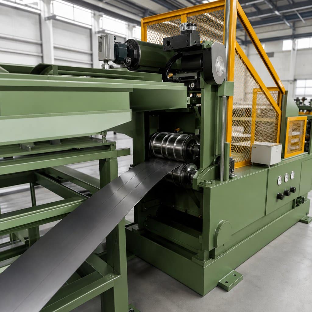
A transformer core cutting line — also called a core cut-to-length line or lamination cutting line — is an automated production line that converts strips of grain-oriented silicon steel (CRGO), typically 0.18–0.35 mm thick, into finished core laminations. It performs fixed-length and fixed-angle transverse cutting (most commonly 45° miters), punching of holes or V-notches where required, and stacking or sorting of the finished pieces.
The line sits between two other processes: upstream, a slitting line cuts wide master coils into strips; downstream, the cut laminations go to core stacking. Because it links material preparation and core assembly, the cutting line largely determines both your material utilization rate and your stacking efficiency.
How Does a Core Cutting Line Work? Key Stages
Stage 1: Decoiling and feeding
The line starts with a decoiler that unwinds the silicon steel strip under controlled tension. A servo-driven feeding system then advances the strip at high speed — up to 240 m/min on modern lines — while maintaining positioning accuracy. Feeding precision is the first contributor to final length tolerance.
Stage 2: Punching and notching
Depending on lamination design, punching units create holes, slots, or V-notches before shearing. On “two shear, two punch” configurations, two punching stations work in coordination with two shear units, allowing complex lamination geometries without slowing the line.
Stage 3: Shearing at precise angles
The shear units cut the strip to length at programmed angles — 45° miters for step-lap joints, or straight cuts for center limbs. This is where cutting accuracy is defined: ±0.1 mm on length, ±0.025° on angle, and burr height ≤0.02 mm are the industry reference values for quality cores.
Stage 4: Sorting and stacking
Finally, finished laminations are conveyed to the stacking area. Basic lines simply accumulate pieces for manual handling; servo sorting lines automatically classify and stack laminations by shape and sequence, ready for direct use at the core stacking table — cutting labor and handling damage at the same time.
The Five Types of Transformer Core Cutting Lines
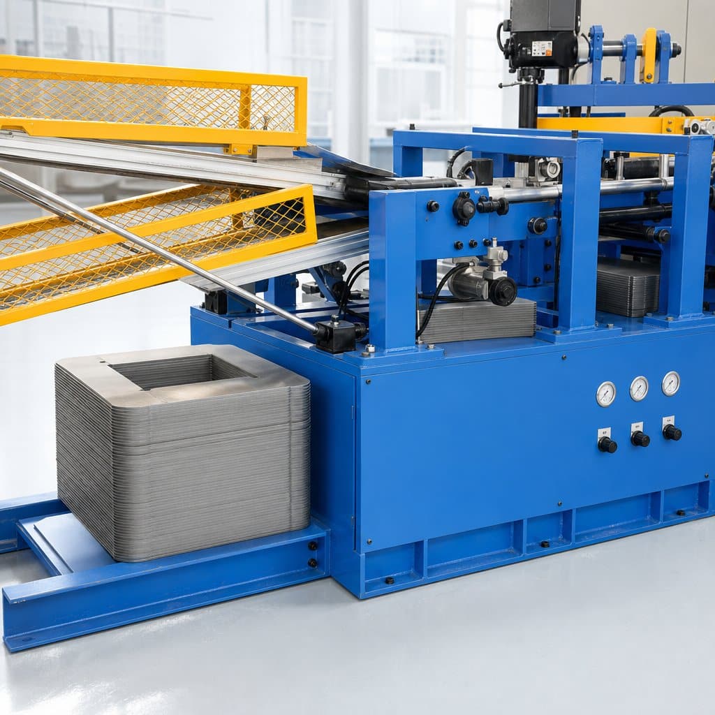
Not every factory needs the same line. The five mainstream configurations differ in positioning method, sorting automation, and coil width capacity:
1. Center positioning line — the stable workhorse
Center-line positioning against the strip centerline delivers consistent accuracy at a cost-effective price. It suits general transformer core production from small distribution units to mid-size power transformers, covering widths of 40–600 mm. For a detailed selection walkthrough, see our center positioning buying guide, and for the mechanics behind the accuracy, the working principle deep-dive. Product details: center position core cutting line.
2. Servo sorting line — for high-volume production
This configuration adds servo-driven automatic sorting and stacking after cutting. If your bottleneck is labor cost or stacking errors rather than cutting itself, servo sorting pays for itself. Our servo stacking buying guide covers the evaluation criteria, and the servo sorting core cutting line page lists the specifications.
3. Servo sorting line for large transformers — wide and heavy
Main power transformers and EHV units need much wider laminations: 150–1000 mm wide coils, lengths up to 5000 mm, and heavier coil handling. The large transformer core cutting line is built with a reinforced structure for exactly this. Selection details are in our main transformer buying guide.
4. Side positioning line — for compact workshops
Side-position feeding simplifies coil loading and shrinks the line’s footprint, at the cost of a narrower width range (40–300 mm) and slightly lower speed (180 m/min). If floor space is your constraint, see the side positioning buying guide and the side position core cutting line product page.
5. Center piece line — for center limbs
Center limbs need different geometries than limbs and yokes. The dedicated center piece core cutting line handles complex center-piece shapes with custom positioning, in a compact 11–12 kW package.
Key Specifications to Compare
Cutting accuracy: the numbers that matter
Three figures define cutting quality. Length accuracy of ±0.1 mm keeps step-lap joints tight; angle accuracy of ±0.025° keeps mitered corners closed; burr ≤0.02 mm prevents inter-laminar shorts. When comparing suppliers, ask for these values in writing — and ask how they are verified.
Width, length, and speed envelope
Match the envelope to your product range, not your current bestseller. Width range (40–300, 60–600, or 150–1000 mm) determines which transformer sizes you can serve; feeding speed (180 vs 240 m/min) determines throughput; length range matters if you build large power transformers with long laminations.
Positioning and sorting method
Positioning method (center vs side) affects both accuracy stability and layout; sorting method (manual accumulation vs servo sorting) affects labor and downstream stacking speed. These two choices drive most of the price difference between configurations.
Automation and integration
Look for recipe storage, automatic tool adjustment, and communication with upstream coil handling and downstream stacking. A line that exchanges data with your stacking area saves more time than raw cutting speed alone.
How to Choose the Right Cutting Line for Your Factory
Based on the five types above, the selection logic is straightforward:
- General production, budget-conscious → center positioning line
- High volume, labor cost pressure → servo sorting line
- Large power / EHV transformers → servo sorting line for large transformers (wide-coil heavy duty)
- Limited workshop space → side positioning line
- Dedicated center limb processing → center piece line
Two final checks before signing: verify that the quoted accuracy values hold at full speed (not just at test speed), and confirm that the sorting output format matches your stacking workflow — otherwise you automate cutting only to create a manual bottleneck downstream.
Frequently Asked Questions
What cutting accuracy should a transformer core cutting line achieve?
The reference values for quality production are ±0.1 mm length accuracy, ±0.025° angle accuracy, and burr height ≤0.02 mm. These tolerances keep core losses and magnetizing current within design targets.
What is the difference between center position and side position lines?
Center positioning references the strip centerline and suits general production with the widest width range; side positioning references one edge, simplifies coil loading, and fits compact workshops but covers narrower strips (40–300 mm).
Is servo sorting worth the investment?
If you run high volumes or struggle with stacking labor, yes. Servo sorting automatically classifies and stacks laminations in sequence, reducing handling errors and feeding the stacking table directly — typically the largest labor saving in the core shop.
Can one line handle both distribution and power transformer laminations?
A 600 mm wide center or servo line covers most distribution and mid-size power transformer needs. For main transformers requiring 800–1000 mm widths and 4000–5000 mm lengths, you need the heavy-duty large-transformer configuration.
Summary: Accuracy First, Automation Second, Envelope Third
Choosing a transformer core cutting line comes down to three questions in order: does it hold ±0.1 mm / ≤0.02 mm burr at production speed; does the sorting level match your labor strategy; does the width envelope match your product roadmap. Answer those, and the right model selects itself.
Planning a core cutting line investment? Send us your lamination drawings and target output — we will recommend the configuration that fits, with verified accuracy data.
📞 Phone: +86-15958243831
📧 Email: sales@tranfovia.com
💬 WhatsApp: https://wa.me/8615958243831
🌐 Website: tranfovia.com
References
- IEC 60076-1: Power transformers — General
- ASTM A876/A876M — Flat-Rolled, Grain-Oriented, Silicon-Iron, Electrical Steel
- IEEE C57.12.00 — General Requirements for Liquid-Immersed Transformers
- IEC 60076-7: Loading guide for oil-immersed power transformers
- CRGO Electrical Steel — Material Fundamentals
- Tranfovia — Transformer Manufacturing Equipment