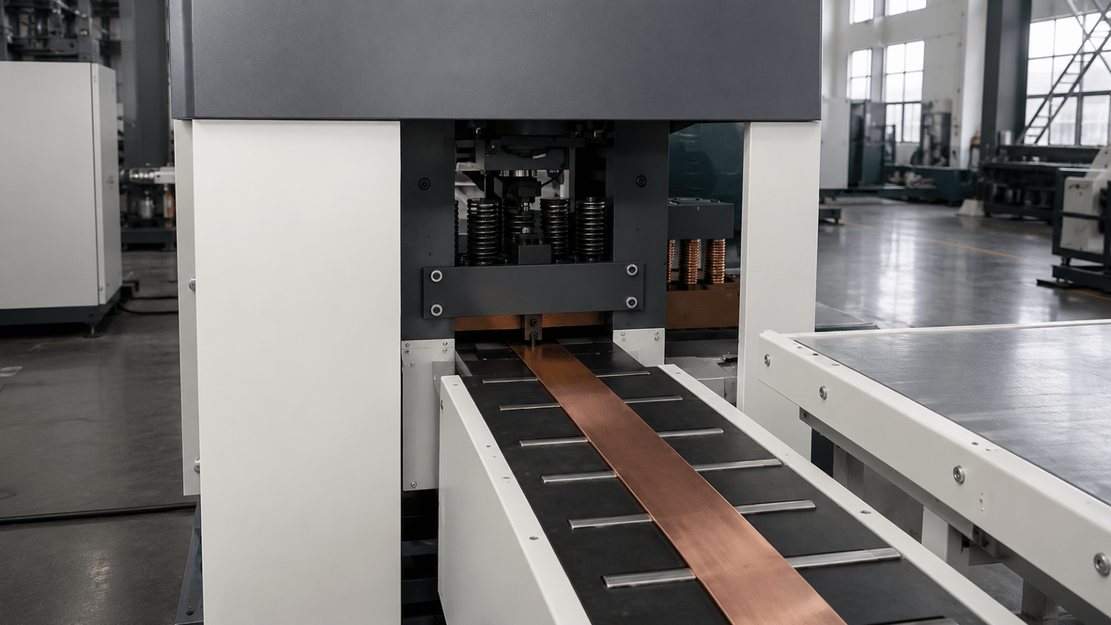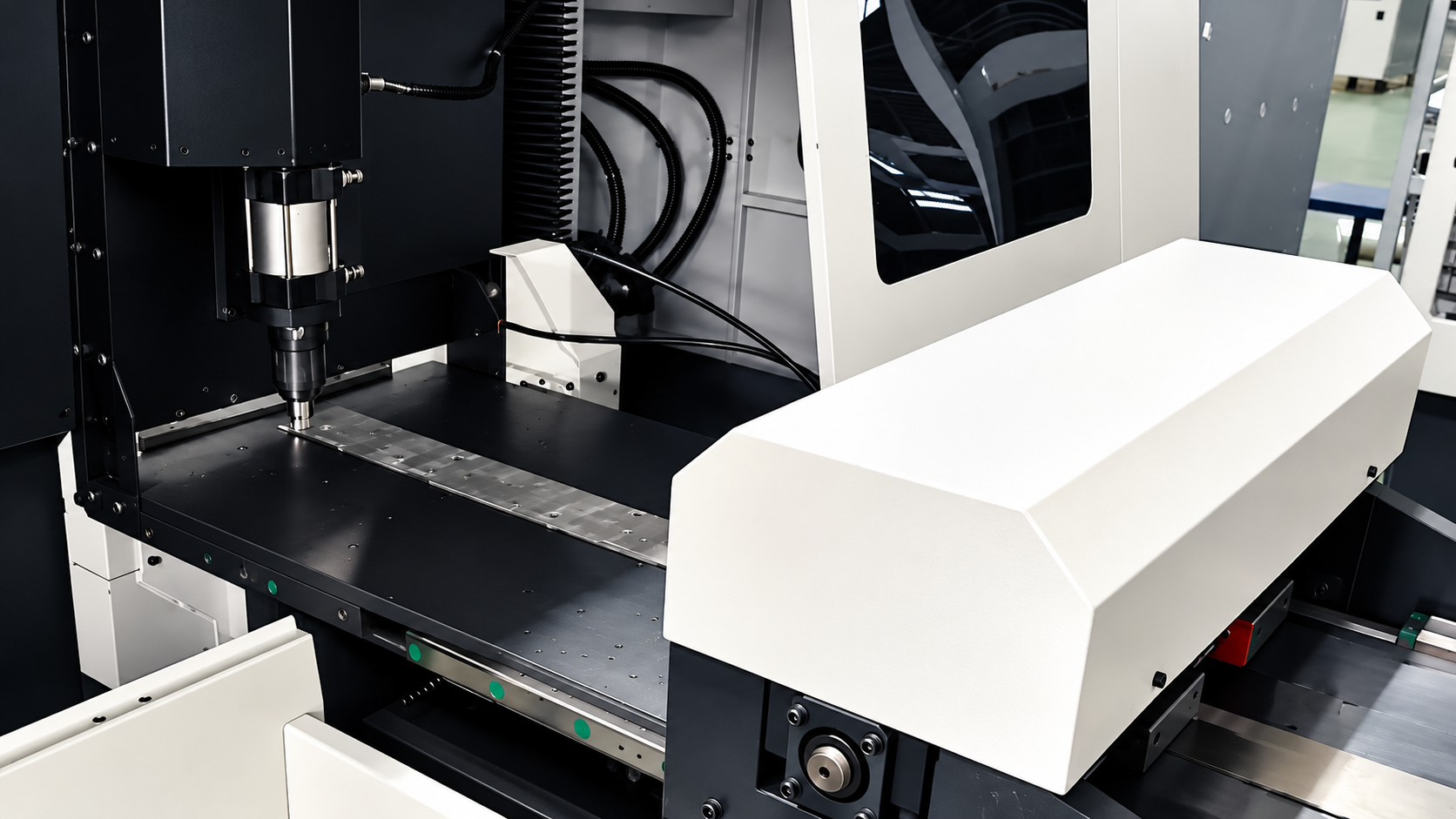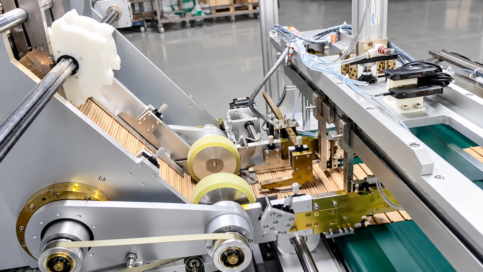
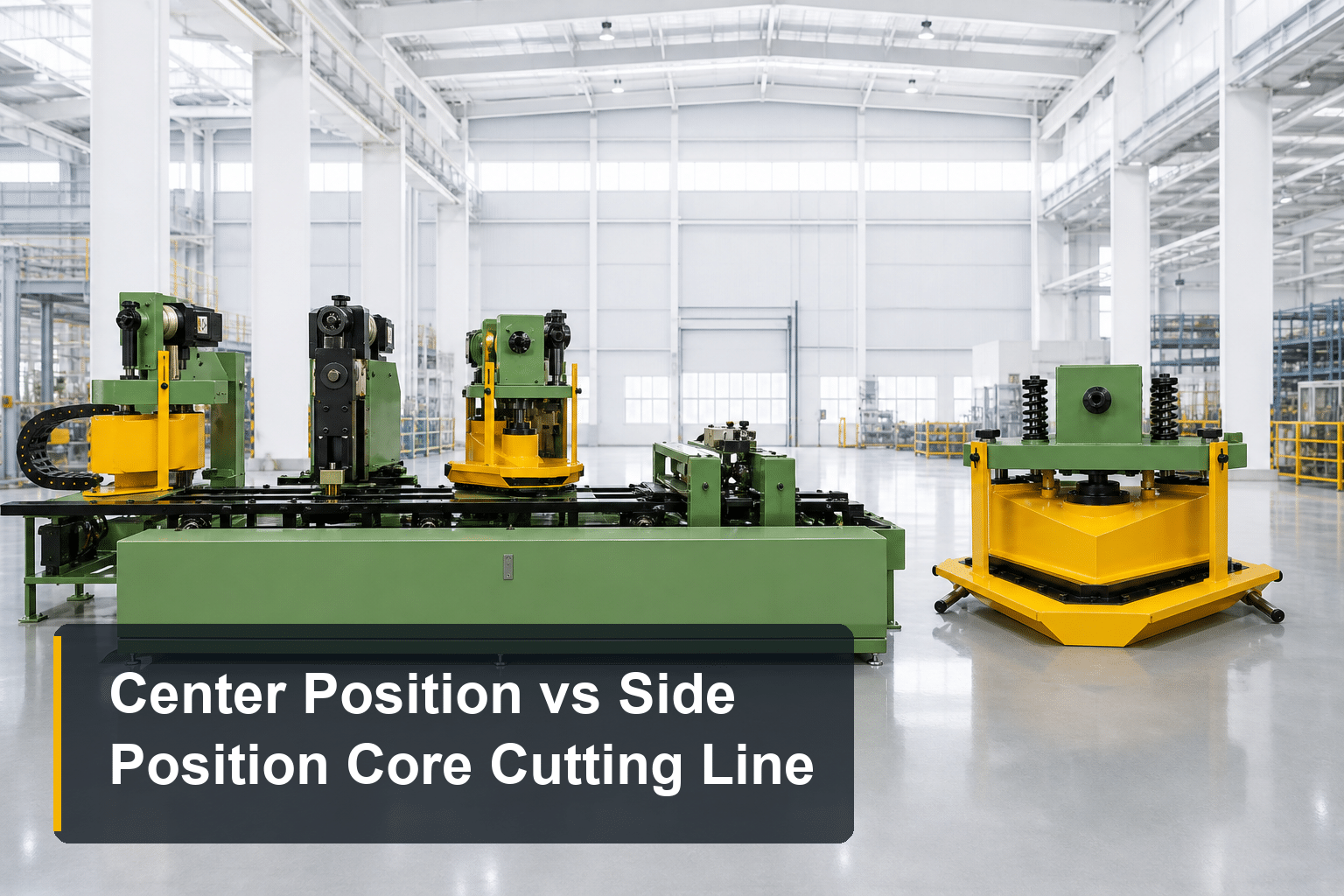
Center position and side position core cutting lines do the same job — decoil CRGO strip, shear it into laminations at ±0.1 mm and ±0.025° — but they reference the strip differently, and that single design choice cascades into width capacity, speed, footprint, and price. If you are choosing between the two, this head-to-head comparison lays out what actually differs and which workshop each design suits.
Same Cut, Different Reference: What Positioning Method Means
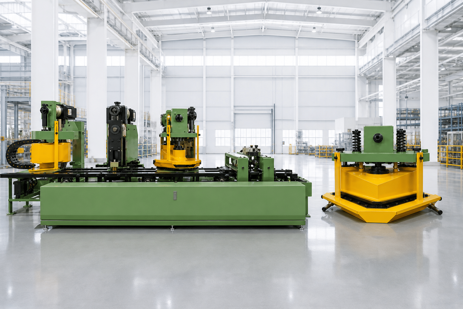
Every cut-to-length line must answer one question before anything else: where is the strip, exactly? The positioning method is how the machine answers it — the reference edge or line against which the strip is guided through the punch and shear stations.
- Center positioning references the strip’s centerline. Guiding elements work from both edges inward, so the strip stays symmetric around the machine’s axis regardless of minor width variation in the coil.
- Side positioning references one edge of the strip. The strip is loaded from the side and held against a fixed guide rail on one face.
Both deliver the same cutting precision at the blade — the differences appear in how much width the line can handle, how fast it runs, how much floor it occupies, and how the operator loads material. For the full five-type landscape, see our guide to transformer core cutting lines.
Center Positioning: The Accuracy-First Design
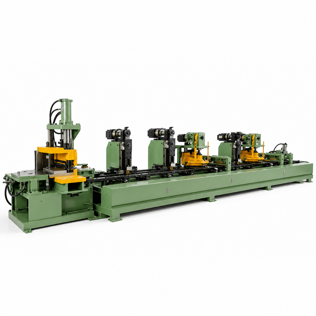
Center-line guiding keeps the strip symmetric around the machine axis. That symmetry pays off in three ways:
- Consistent accuracy across the full width range. Because the strip is always centered, punch and shear stations engage the material identically whether the strip is 40 mm or 600 mm wide. Off-center stress simply does not develop.
- Wider envelope. The center position range runs to 600 mm width and 3,500 mm length on the XE-LL-600ZX — covering mid-size power transformers, not just distribution units.
- Higher speed. Center-guided strip runs at 240 m/min, a third faster than side-positioned feeding, because balanced guidance tolerates higher feed rates without edge wander.
- Thinner material window. The range starts at 0.18 mm, covering the thinnest high-grade CRGO used in low-loss cores.
The mechanism behind this is worth understanding. Opposing guide rollers close symmetrically onto both strip edges and self-center the material before every measured feed. Coil-to-coil width variation — a normal feature of slit CRGO — is absorbed by the guides instead of showing up as positional error at the shear. On a side-referenced line, that same variation would push the far edge of a wide strip off its ideal path.
The trade-off: center positioning mechanisms add mechanical content and cost, and the line occupies more floor space. Our center positioning buying guide walks through model selection in detail.
Side Positioning: The Compact, Accessible Design
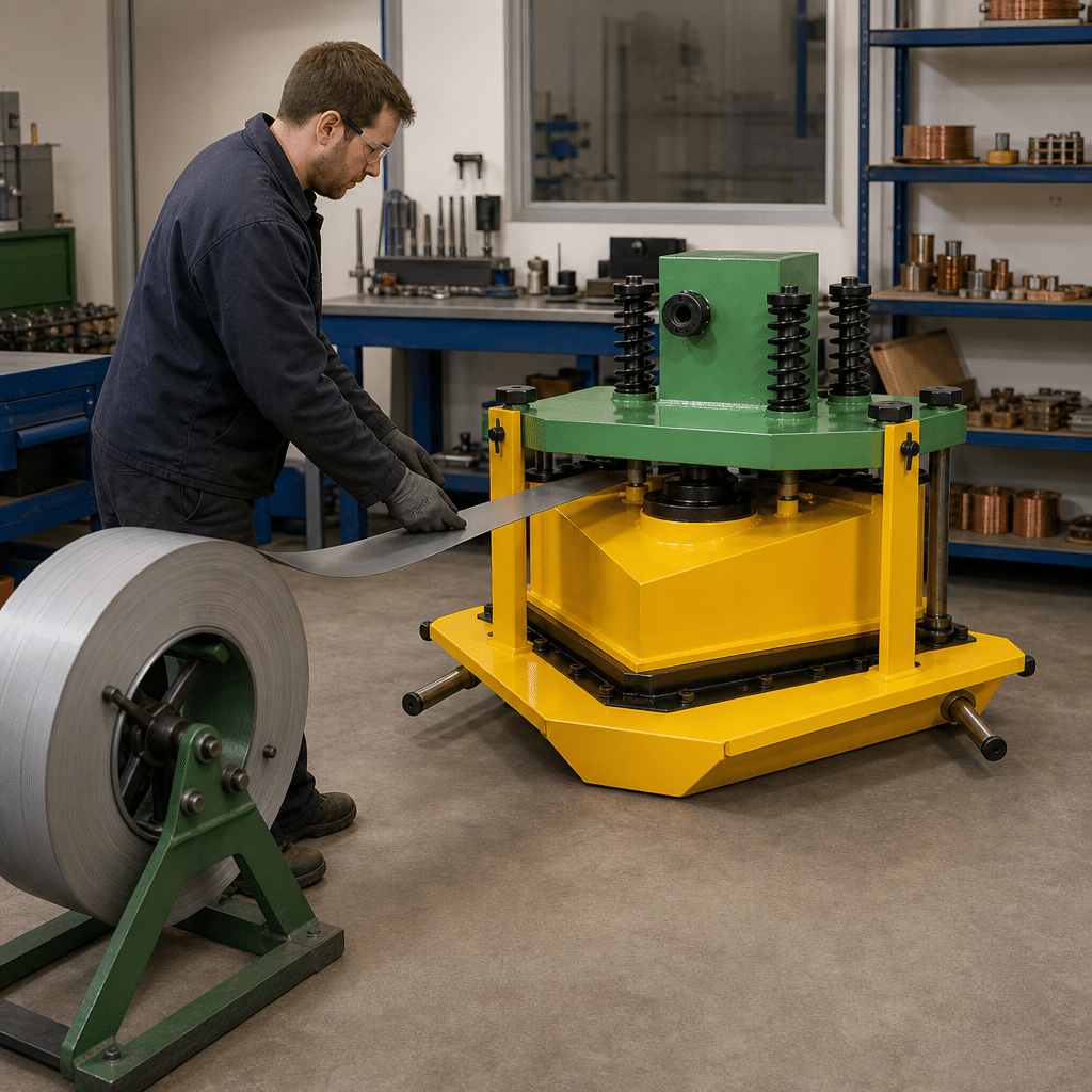
Side positioning references one strip edge against a fixed guide. The design trades envelope for practicality:
- Smaller footprint. Side loading shrinks the line’s width — the deciding factor when floor space is the constraint.
- Easier coil loading. The operator loads from the side with clear access, instead of threading strip into a center-guided path.
- Lower entry cost. Fewer guiding mechanisms and a simpler frame make this the economical way into automated cutting.
The limits follow from the design: width tops out at 300 mm, feeding runs at 180 m/min, and the thickness window starts at 0.23 mm. For distribution-class cores within that envelope, cutting quality is identical — ±0.1 mm length, ±0.025° angle, ≤0.02 mm burr. See our side positioning buying guide for the full selection walkthrough.
It is worth being precise about what “compact” buys you. Side loading removes the clearance a center-guided path needs on both flanks of the line, so the machine can sit closer to a wall or another line. In a leased building where every square meter carries rent, that difference can outweigh a speed advantage you would rarely use.
Head-to-Head: Specifications Compared
| Item | Center Position (XE-LL-ZX series) | Side Position (XE-LL-Z series) |
|---|---|---|
| Positioning reference | Strip centerline, dual-side guiding | One strip edge, side loading |
| Cutting width | 40–600 mm (three models) | 40–300 mm (two models) |
| Cutting length | 350–3500 mm | 350–2000 mm |
| Cutting thickness | 0.18–0.35 mm | 0.23–0.35 mm |
| Feeding speed | 240 m/min | 180 m/min |
| Length accuracy | ±0.1 mm | ±0.1 mm |
| Angle accuracy | ±0.025° | ±0.025° |
| Cutting burr | ≤0.02 mm | ≤0.02 mm |
| Footprint & loading | Larger; center-guided threading | Compact; open side access |
The table makes the situation plain: precision is identical, so the decision is never about cut quality. It is about envelope (width, length, thickness), throughput (240 vs 180 m/min), and workshop practicalities (footprint, loading, budget).
Which One Fits Your Workshop?
Work through four questions in order:
- What is your widest lamination? Above 300 mm, center positioning is the only option. At or under 300 mm, both qualify — continue.
- What is your daily volume? If output is throughput-limited, 240 m/min center positioning produces a third more per shift. If the line waits on downstream stacking anyway, 180 m/min is not a real constraint.
- How tight is your floor space? A compact workshop that cannot fit the center-positioned line’s width makes the decision for you — side positioning exists for exactly this case.
- Do you cut thin, high-grade CRGO (0.18–0.23 mm)? Only the center position range covers it.
The typical outcomes: growing factories with mixed distribution and mid-size production choose center positioning for headroom; dedicated distribution-transformer shops in tight buildings choose side positioning and never miss the extra width.
One scenario deserves a mention: factories that do both. A plant running high-volume distribution cores on side position lines and occasional mid-size power cores may justify one center position line alongside them — using each design where its strengths apply, rather than forcing one machine class to cover everything. The breakpoint is utilization: a center position line running only narrow strip is capacity paid for and never used.
Conclusion
Center position vs side position is not a quality decision — both hold identical cutting tolerances. It is an envelope and layout decision: width above 300 mm, thin material, or maximum throughput points to center positioning; compact workshops and distribution-class production point to side positioning. If you are still unsure, send us your lamination drawings and floor plan — we will tell you which line fits, and why.