TL;DR:
- A transformer core cut-to-length line (side positioning) references the strip against one edge, offering a compact footprint and simplified coil loading for narrow-strip production.
- Compare cutting accuracy (±0.1 mm length, ±0.025° angle, ≤0.02 mm burr) together with the positioning method — side referencing suits asymmetrical shapes and tight workshops.
- Match the model to narrow strips (40–300 mm), moderate speeds (180 m/min), and space-constrained layouts rather than to maximum throughput.
- Verify accuracy on your own strip and confirm layout drawings fit your floor before buying.
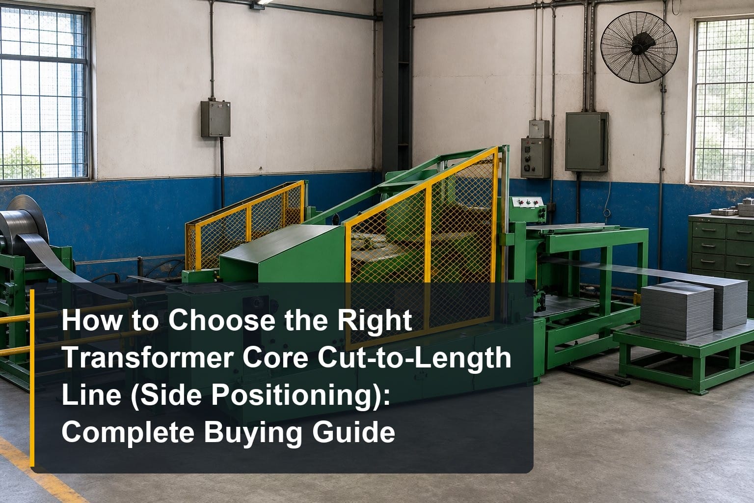
How to choose the right transformer core cut-to-length line (side positioning) starts with understanding what side referencing actually buys you: a compact machine, simple loading, and precise edge-referenced cutting for narrow strip. This article explores what the machine is and how it fits into transformer manufacturing, which specifications to compare, how to match a model to your application, and the questions to ask any manufacturer or supplier, providing a practical framework for buyers of smaller core production equipment.
What a Transformer Core Cut-to-Length Line (Side Positioning) Is
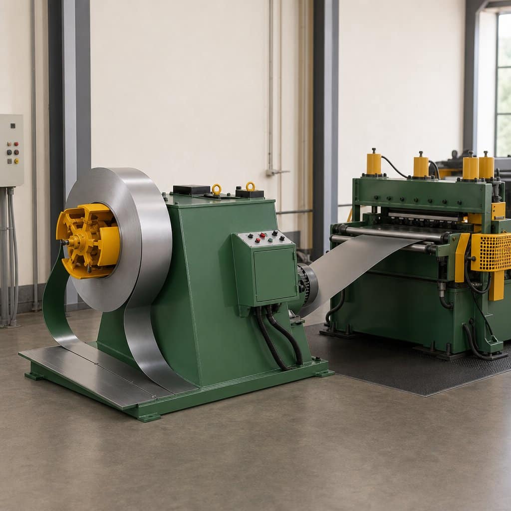
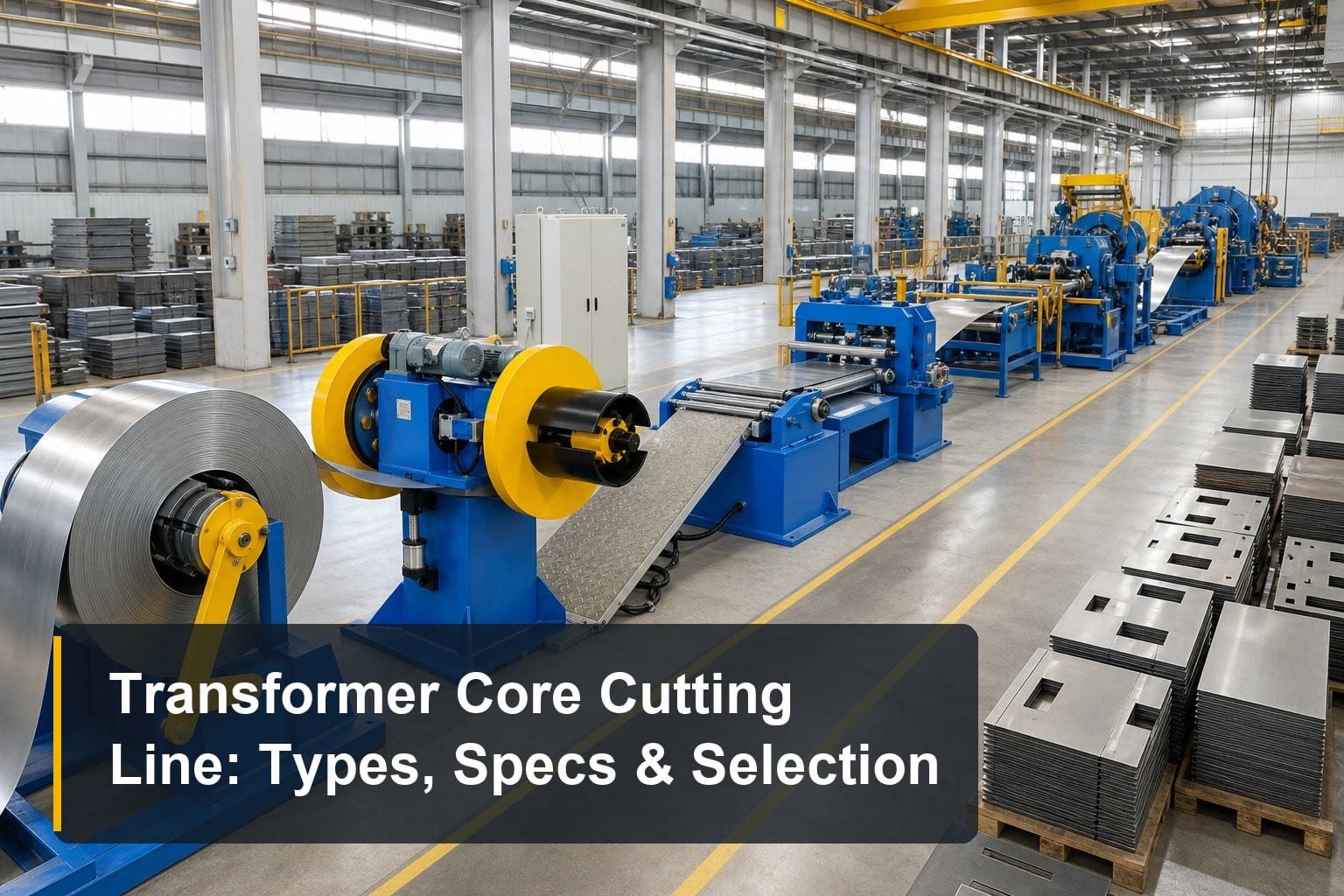
A side-positioning cut-to-length line is the compact, edge-referenced member of the core cutting family. It feeds silicon steel strip along a side datum, punches and shears it into laminations, and does so in a footprint noticeably smaller than center-positioning designs. Knowing what this layout optimizes for — and what it gives up — is the first step in choosing well.
Definition and Core Function
In simple terms, a transformer core cut-to-length line (side positioning) unwinds grain-oriented silicon steel, guides the strip against a fixed side reference edge, and cuts it into laminations of programmed length with punch holes and notches as required. Because all dimensions are measured from one edge, the machine needs no symmetrical centering mechanism, which simplifies the structure, shortens the line, and makes the strip path easier to load and thread. Typical models handle strips from 40 to 300 mm wide and 0.23 to 0.35 mm thick.
Where It Fits in Transformer Manufacturing
The line fills the same slot between slitting and core stacking as any cutting line, but it serves a specific niche: narrow-strip production for small and medium distribution transformer cores, reactor and inductor cores, and workshops where floor space is genuinely constrained. The side-feeding arrangement lets the decoiler sit alongside rather than in line, so the cell can wrap around columns or fit into corners that an inline layout cannot use. For factories where every square meter is planned, this layout flexibility is a real economic advantage.
Side Positioning vs. Center Positioning
Center positioning references the strip’s centerline and distributes width variation symmetrically — ideal for symmetrical step-lap cores at high speed. Side positioning references one edge, which suits asymmetrical shapes, narrow strips, and designs where one edge is the functional datum. The trade-offs are speed and width range: side-positioning lines typically run at 180 m/min against 240 m/min for center-positioning models, and cover narrower strips. Buyers running symmetrical EI cores at high volume should compare against a center-position core cutting line before committing to either layout.
Key Specifications to Compare
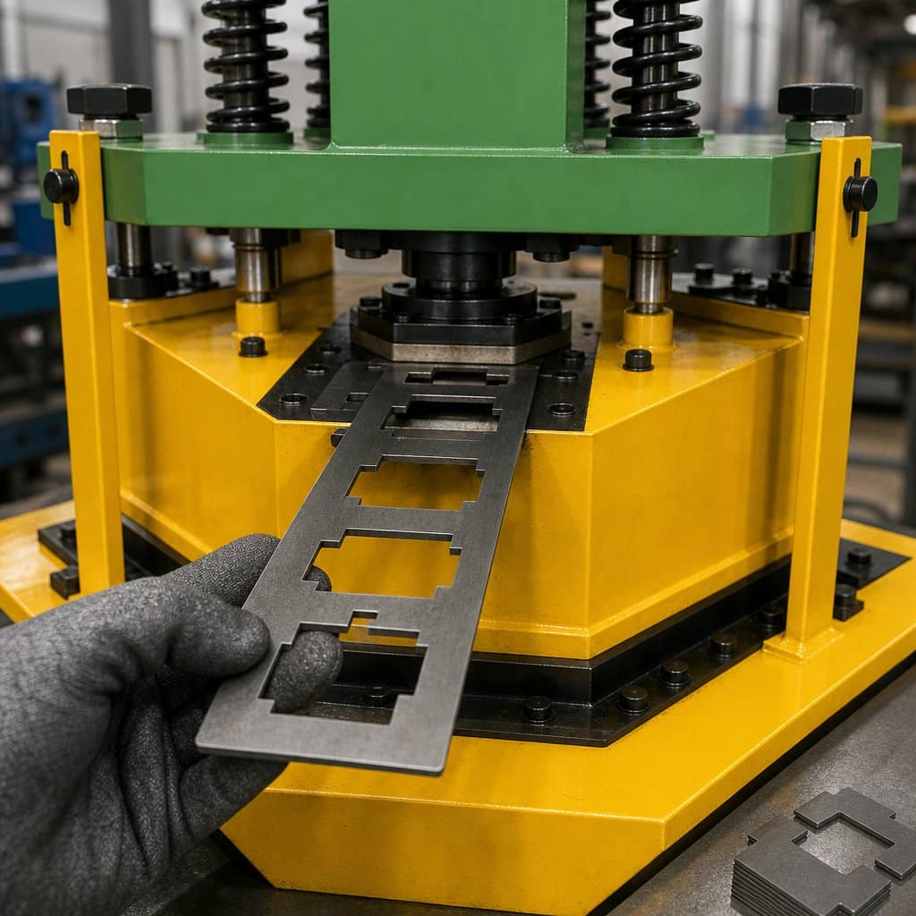
Choosing a transformer core cut-to-length line (side positioning) means verifying that the compact structure does not compromise the fundamentals. Three specification groups matter: cutting accuracy, the positioning system itself, and the practical numbers — speed, width, and footprint.
Cutting Accuracy: Length, Angle, and Burr
The accuracy standard does not drop because the machine is smaller: length tolerance of ±0.1 mm, cutting angle accuracy of ±0.025° for mitered step-lap cuts, and burr height at or below 0.02 mm on grain-oriented steel remain the figures to demand. On narrow strip these tolerances are easier to hold than on wide strip, so a well-built side-positioning line should guarantee them at full rated speed, not just during slow setup runs. Confirm the shear blade material and gap adjustment range for your strip thickness before accepting the numbers.
Positioning Method and Edge Reference Quality
With side positioning, the reference edge is everything. Ask how the side guide is constructed and adjusted: hardened wear strips, fine lateral adjustment, and positive strip contact without excessive pressure that could buckle thin material. Because all dimensions derive from one edge, any damage or burr on the strip’s reference side propagates into every measurement — so slit-edge quality from your upstream slitting process matters more here than with center referencing. A good supplier will ask about your slit strip quality before recommending this layout.
Speed, Width Range, and Footprint
Rated feeding speed around 180 m/min is realistic for this class; effective output depends more on cut cycle time and changeover than on peak feed rate. Verify the working envelope — 40–300 mm width and 350–2,000 mm length on typical models — against your drawings. Then measure the footprint claim: request an actual layout drawing with decoiler position, operator access, and discharge direction, and check it against your floor plan. The space saving that justifies this machine only counts if the delivered layout truly fits.
Matching the Right Model to Your Application
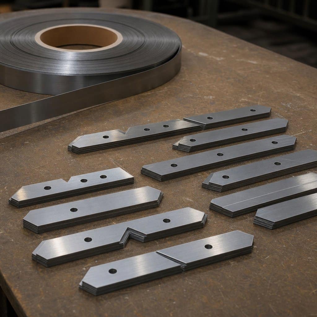
The right transformer core cut-to-length line (side positioning) is the one whose envelope covers your narrow-strip designs and whose layout solves a real constraint in your workshop. Three factors drive the match.
Strip Width and Core Design Mix
Start with your strip widths. Side-positioning lines serve the 40–300 mm range, which covers small and medium distribution cores, reactor cores, and inductor laminations. If your mix is dominated by narrow strips and asymmetrical shapes, this layout fits naturally. If wide symmetrical step-lap cores are your main product, a center-positioning line is the better foundation — many factories eventually run both, each doing what it does best. Also check thickness: this class covers 0.23–0.35 mm, so confirm your steel grades fall inside it.
Volume, Speed, and Secondary Material
Match speed to realistic output. At 180 m/min with fast changeover, a side-positioning line comfortably feeds one or two shifts of small-core production; it is not the tool for maximum-tonnage programs. One application where this class excels is processing narrow remnant strips and secondary material into usable laminations — if reclaiming offcuts matters to your material economics, compare with a dedicated secondary material silicon steel cutting line to see which handles your remnant mix better.
Workshop Layout and Future Expansion
Document your constraint before shopping: available length and width, column positions, crane coverage for coil loading, and forklift paths. The side-feeding layout earns its premium when it turns unusable floor into productive floor. Also think ahead — if volume grows, will you add a second compact line or replace this one with a faster center-positioning machine? A compact line retains its value as a secondary or specialty machine, so buying compact first and adding capacity later is a lower-risk path than the reverse.
Questions to Ask the Manufacturer or Supplier
A side-positioning line is often a first machine or a space-driven purchase, so supplier support during layout, installation, and ramp-up matters disproportionately. These questions test whether a supplier understands the compact-line niche.
Can You Prove Accuracy on My Strip?
Request a factory acceptance test on your own material: your narrowest and widest strips, your most common lamination lengths, and your actual step-lap patterns. The supplier should deliver measured length, angle, and burr data from that run at rated speed. When evaluating a specific model such as a side-position core cutting line, also ask for the side-guide adjustment range and wear-part list, because the reference edge is the component your accuracy depends on every single shift.
Will the Layout Fit — and Who Verifies It?
Ask for a dimensioned layout drawing showing the decoiler, strip path, operator stations, and discharge, and walk it against your floor plan together with the supplier. Clarify who is responsible if the delivered machine does not fit the agreed layout, and whether installation and leveling are included. A supplier experienced with space-constrained installations will ask for your floor drawing before quoting rather than after shipping.
What After-Sales Support Do You Provide?
Compact lines are often run by small teams without dedicated maintenance staff, so clarify the support package in writing: commissioning and operator training, spare-parts list for blades and guide strips, remote diagnostics, and response-time commitments. Ask how guide wear is detected and corrected, and what the first-year maintenance plan covers. A supplier offering pre-shipment inspection, clear documentation, and responsive technical contact will cost less over the machine’s life than a cheaper quote with vague terms.
Frequently Asked Questions
What is side positioning on a core cutting line?
Side positioning guides the silicon steel strip against a fixed reference edge on one side rather than centering it. All cutting dimensions derive from that edge. The arrangement simplifies the machine structure, shortens the line, and allows a compact layout with the decoiler alongside — at the cost of lower top speed and a narrower strip range than center-positioning designs.
When should I choose side positioning over center positioning?
Choose side positioning when your production is narrow strips (up to about 300 mm), asymmetrical shapes, or edge-referenced designs — and when floor space or loading access is genuinely constrained. Choose center positioning for symmetrical EI and step-lap cores at higher volumes, where its 240 m/min speed and balanced edge margins pay off. Many factories run one of each for different product families.
Does a compact line sacrifice cutting accuracy?
It should not. A well-built side-positioning line holds the same ±0.1 mm length tolerance, ±0.025° angle accuracy, and ≤0.02 mm burr as larger machines — on narrow strip these are actually easier to hold. What it gives up is speed (around 180 m/min) and width range, not precision. Verify the figures on your own material during acceptance testing.
Can a side-positioning line handle step-lap cores?
Yes, provided the punch and shear units are CNC-controlled with miter and notch capability. Step-lap laminations with 45° miters, V-notches, and holes are standard work for this class. Confirm the punching capacity for your patterns and that recipe changeover between your core designs is program-based rather than mechanical.
Summary
Choosing the right transformer core cut-to-length line (side positioning) means playing to its strengths: edge-referenced precision on narrow strip, a compact footprint that fits constrained workshops, and simple loading that small teams appreciate — while accepting its honest limits of 180 m/min and a 40–300 mm envelope. Verify ±0.1 mm accuracy on your material, confirm the layout drawing against your floor, and secure clear after-sales terms before you buy.
TRANFOVIA supplies side-position core cutting lines in 300 and 400 mm classes, with layout engineering, factory acceptance testing, and responsive after-sales support. For a recommendation matched to your strip widths and floor plan, contact TRANFOVIA today.
📞 +86-15958243831 📧 sales@tranfovia.com 💬 WhatsApp: https://wa.me/8615958243831 🌐 tranfovia.com
References
- IEC 60076-1:2011. Power transformers — Part 1: General. International Electrotechnical Commission. https://webstore.iec.ch
- IEEE Std C57.12.00-2015. IEEE Standard for General Requirements for Liquid-Immersed Distribution, Power, and Regulating Transformers. IEEE. https://standards.ieee.org
- ASTM A876/A876M. Standard Specification for Flat-Rolled, Grain-Oriented, Silicon-Iron, Electrical Steel. ASTM International. https://www.astm.org
- IEC 60404-8-7. Magnetic materials — Specifications for individual materials — Cold-rolled grain-oriented electrical steel. International Electrotechnical Commission. https://webstore.iec.ch
- Kulkarni, S. V., & Khaparde, S. A. (2004). Transformer Engineering: Design and Practice. Marcel Dekker.
- Georgilakis, P. S. (2009). Spotlight on Modern Transformer Design. Springer.