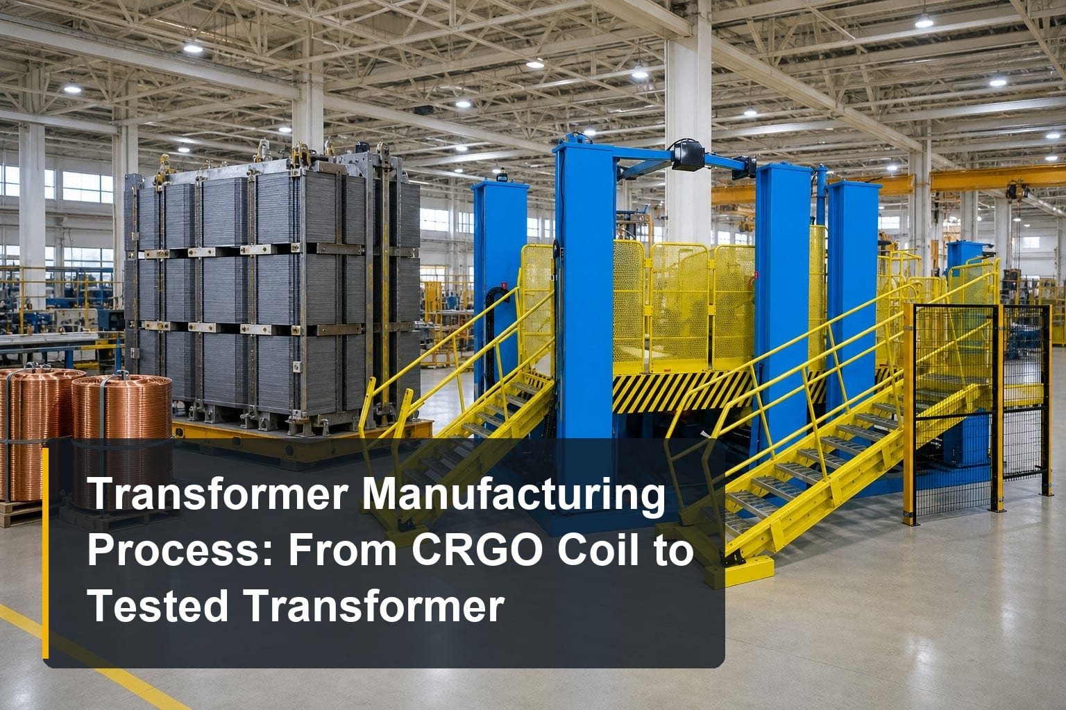
TL;DR: The transformer manufacturing process runs through six connected stages: silicon steel slitting and cut-to-length cutting, core stacking and assembly, coil winding, insulation component manufacturing, drying/impregnation and oil filling, then final assembly and testing. Each stage has dedicated equipment, and the accuracy of upstream steps (like ±0.1 mm cutting length and ≤0.02 mm burr) directly determines downstream quality. This guide walks through every stage, the machines involved, and the parameters that matter.
Whether you are planning a new transformer factory, upgrading a single workshop, or sourcing equipment for the first time, understanding the complete transformer manufacturing process is the foundation of every good purchasing decision. A power transformer is not built by one machine — it is the result of a coordinated production chain where each stage feeds the next. In this guide, we break down the full process from CRGO coil to tested transformer, stage by stage, with the equipment and quality parameters that experienced manufacturers watch most closely.
Overview: The Six Stages of Transformer Manufacturing
A typical oil-immersed or dry-type transformer production line can be divided into six stages:
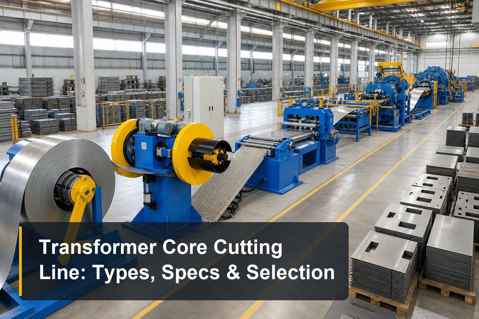
- Core material processing — slitting wide CRGO coils into strips and cutting them into laminations
- Core stacking and assembly — building the magnetic core from cut laminations
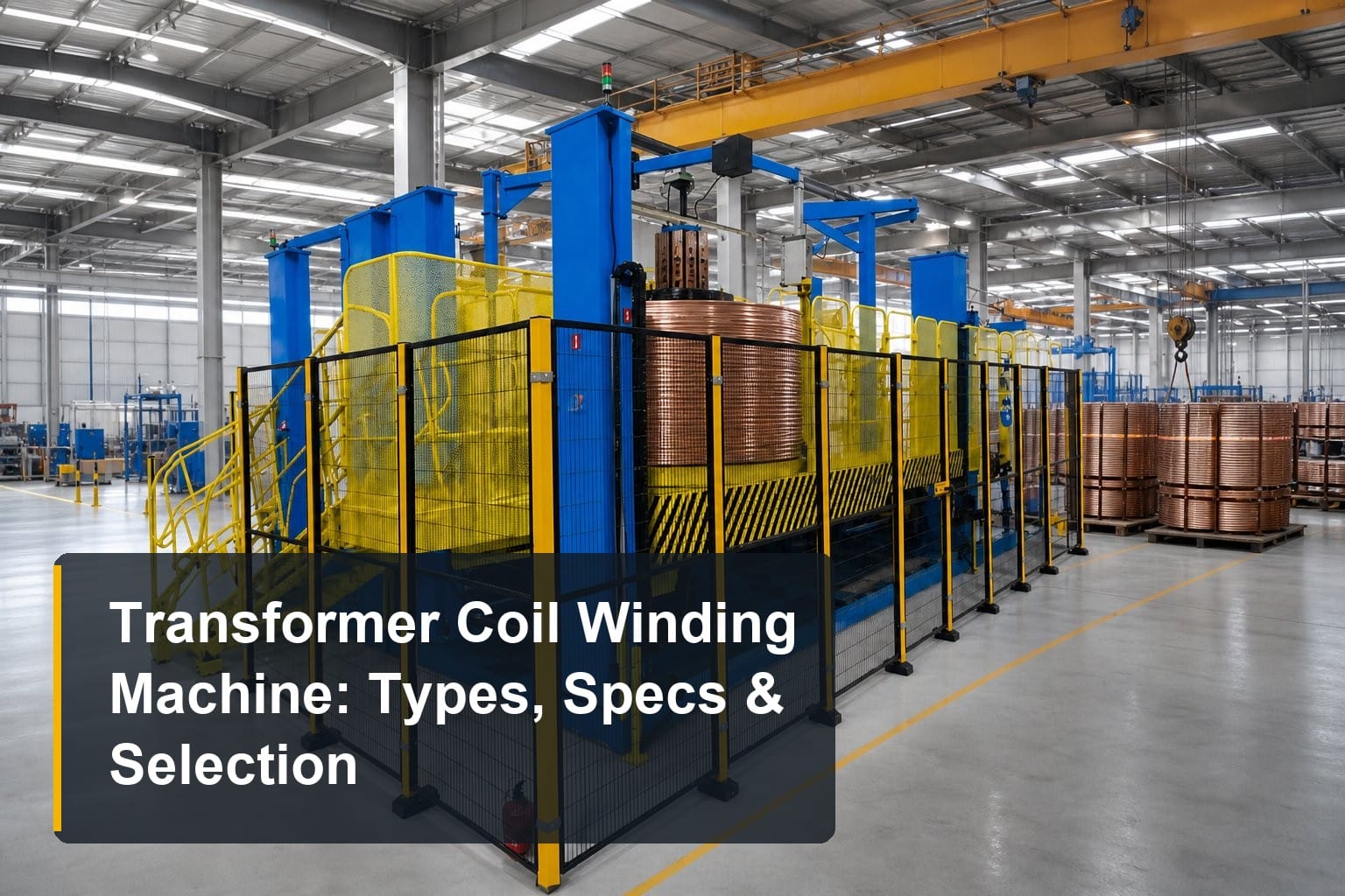
- Coil winding — winding HV and LV coils from wire or foil
- Insulation component manufacturing — producing pressboard parts, spacers, cylinders, and end rings
- Drying, impregnation, and oil filling — removing moisture and impregnating insulation
- Final assembly and testing — tanking, bushing installation, and routine tests
Each stage below explains what happens, which machines do the work, and which specifications actually affect transformer performance.
Stage 1: Core Material Processing — Slitting and Cut-to-Length Cutting
From CRGO coil to strip
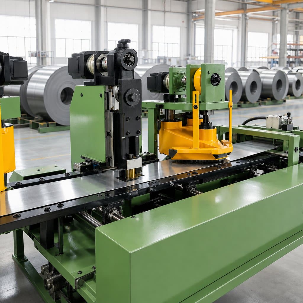
Transformer cores start as wide coils of grain-oriented silicon steel (CRGO), typically 0.18–0.35 mm thick. The first operation is longitudinal slitting: a silicon steel slitting line unwinds the master coil and cuts it into narrower strips at speeds up to 120 m/min. Burr control here is critical — a burr level of ≤0.02 mm is the accepted benchmark, because burrs create inter-laminar short circuits that raise no-load losses.
Cutting laminations to length and angle
Slit strips then move to cut-to-length lines, which shear laminations to precise lengths and miter angles (commonly 45°) for core limbs and yokes. Modern lines such as a center position transformer core cutting line achieve cutting length accuracy of ±0.1 mm and angle accuracy of ±0.025° at feeding speeds of 240 m/min. Variants exist for different factory needs: servo sorting lines add automatic lamination stacking, heavy-duty models handle 1000 mm wide coils for large power transformers, and side-position lines fit space-constrained workshops.
Why this stage decides downstream quality
Every stacking, winding, and assembly step inherits the dimensional accuracy of the cut laminations. Poor length consistency forces manual rework during stacking and increases the air gaps in the core — which directly raises magnetizing current and noise.
Stage 2: Core Stacking and Assembly
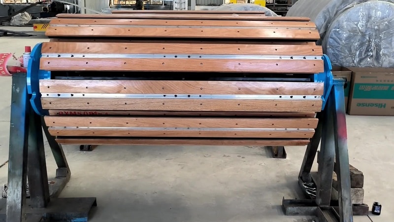
Cut laminations are stacked into three-limb or five-limb cores, traditionally on flat tables — a labor-intensive step where stacking accuracy determines core losses. A transformer core stacking and turning table lets workers stack horizontally at an ergonomic height, then turns the finished core 90° using the workshop crane — no pit, no foundation, and no extra power consumption. Well-built tables keep deformation within 3 mm during turning and vertical deviation within 2 mm after turning. After turning, cores are bound with tape or non-woven belts by a core binding machine before coil insertion.
Stage 3: Coil Winding
HV and LV coils are different products
High-voltage coils are typically wound from enameled round or flat wire, while low-voltage coils in modern designs increasingly use copper or aluminum foil. The two require fundamentally different machines: wire winding demands precise turn counting and tension control, while foil winding demands alignment accuracy within ±0.5 mm and constant foil tension.
Choosing the winding platform
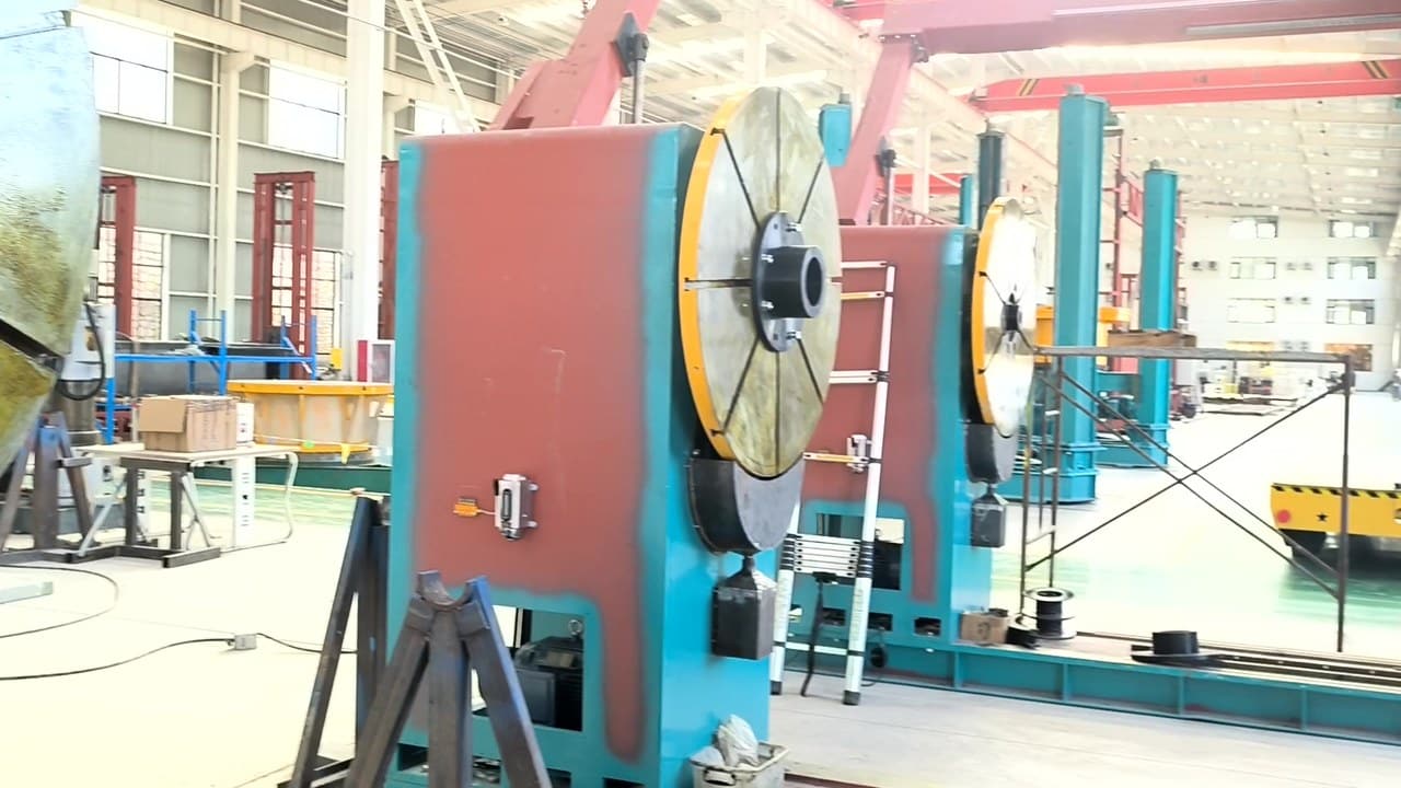
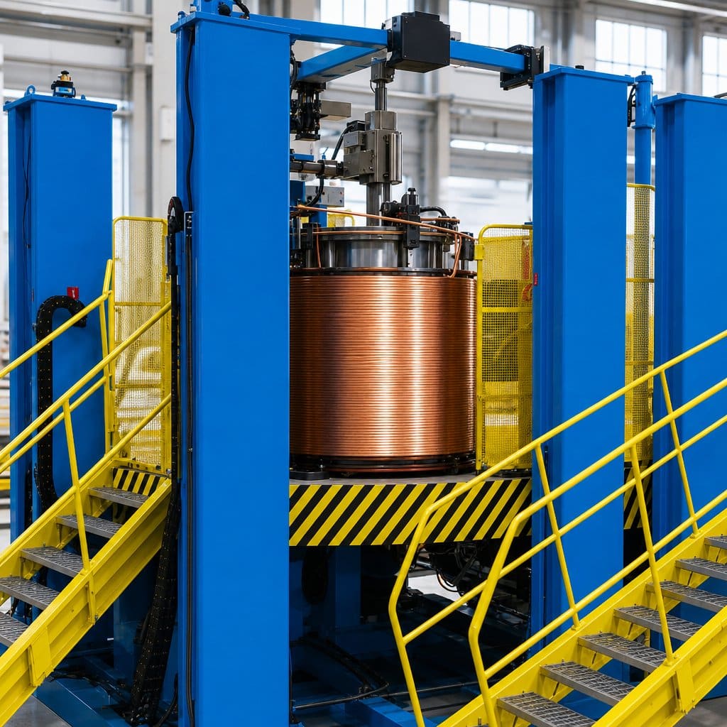
Large power transformer coils — continuous disc or interleaved types weighing several tons — are usually wound on a vertical winding machine, where a chuck elevation system adjusts coil height while the operator platform stays fixed. Distribution transformer HV coils run on automatic horizontal winding machines with PLC and servo control at up to 280 rpm. Whatever the platform, a tension pay-off stand is the accessory that protects wire quality: constant tension prevents loose turns and can save 1.5–2 kg of copper per 1000 kVA coil.
Stage 4: Insulation Component Manufacturing
A transformer contains far more insulation engineering than most buyers expect: pressboard cylinders between windings, end rings, dovetail spacers forming cooling ducts, lead insulation, and electrostatic shielding rings. These parts come from a dedicated insulation workshop: multi-layer heat presses laminate pressboard, CNC shears and saws cut panels, beveling machines mill slope edges for cylinder joints, and specialized machines shape spacers, wrap leads, and mark end rings. Dimensional consistency in this stage determines both dielectric strength and the oil-flow cooling paths inside the transformer.
Stage 5: Drying, Impregnation, and Oil Filling
Removing moisture is non-negotiable
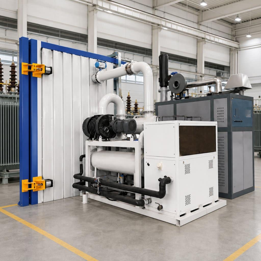
Cellulose insulation absorbs moisture from the air, and even a fraction of a percent of residual water sharply reduces dielectric strength and accelerates aging. After coil assembly, the active part goes through vacuum or vapour-phase drying. Vacuum drying equipment lowers the boiling point of water so moisture evaporates at safe temperatures; vapour phase drying uses solvent vapour as the heat-transfer medium for faster, deeper drying of large or UHV units. Constant-pressure compaction devices keep coils compressed during drying so insulation does not shrink unevenly.
Impregnation and oil filling under vacuum
Dry-type coils are often impregnated with varnish or resin through VPI (vacuum pressure impregnation) or vacuum casting. Oil-immersed transformers are filled with degassed insulating oil under vacuum — equipment with an ultimate vacuum around 10 Pa and combined flowmeter + level-gauge control, such as modern vacuum oil filling equipment, ensures no air bubbles remain trapped in the insulation structure.
Stage 6: Final Assembly and Testing
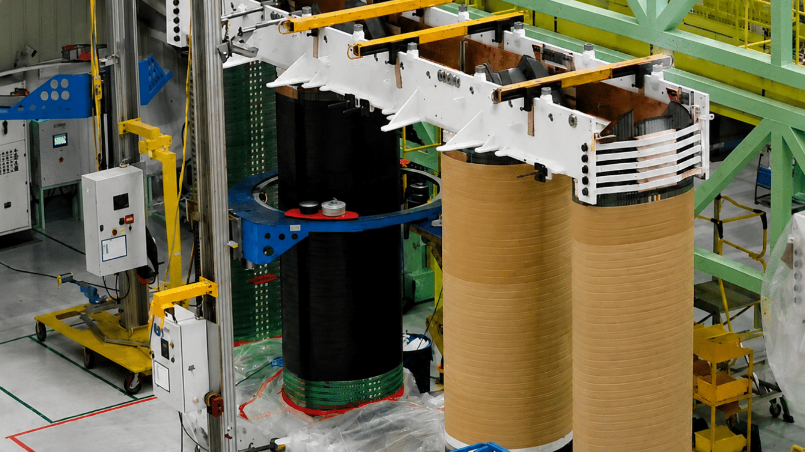
In the final stage, the dried active part is tanked; bushings, tap changers, radiators, and accessories are installed; and the transformer undergoes routine tests — ratio, resistance, insulation, induced and applied voltage, and no-load/load loss measurements per IEC 60076. Assembly platforms, coil lifting beams, and coil assembly platforms support safe handling of heavy components throughout this stage. Only after passing all routine tests is the transformer ready for dispatch.
Frequently Asked Questions
What is the most critical stage in the transformer manufacturing process?
Most manufacturers point to core cutting and drying. Cutting accuracy (±0.1 mm length, ≤0.02 mm burr) sets the ceiling for core losses, while incomplete drying permanently compromises insulation life. Investing in these two stages usually delivers the fastest quality return.
How long does it take to manufacture a power transformer?
A distribution transformer typically takes 2–4 weeks from material to dispatch; large power transformers can take 2–6 months, with drying and impregnation alone occupying several days to weeks depending on voltage class.
Can one factory produce both distribution and power transformers?
Yes, but the equipment envelope differs — wider coil stock (up to 1000 mm), heavier winding machines (up to 45 T), and larger drying tanks are needed for main transformers. Many factories run two parallel equipment configurations.
What should I budget first when setting up a transformer production line?
Start with the core cutting line and winding machines — they define your product range. Drying and oil-filling equipment follows the voltage class you target. A staged investment plan aligned with your product roadmap avoids over- or under-capacity.
Summary: Build the Process, Then Buy the Machines
The transformer manufacturing process is a chain: slitting and cutting set dimensional accuracy, stacking builds the magnetic circuit, winding creates the electrical circuit, insulation components protect it, drying and oil filling preserve it, and testing proves it. Equipment decisions made stage-by-stage — with real specifications like burr ≤0.02 mm, winding tension stability, and 10 Pa vacuum — always outperform decisions made machine-by-machine in isolation.
Need help planning your production line? Tranfovia supplies equipment for every stage described above — from slitting and cutting lines to winding machines, insulation processing, and vacuum drying systems. Tell us your transformer types and target capacity, and we will propose a matched equipment list.
📞 Phone: +86-15958243831
📧 Email: sales@tranfovia.com
💬 WhatsApp: https://wa.me/8615958243831
🌐 Website: tranfovia.com
References
- IEC 60076-1: Power transformers — General
- IEEE C57.12.00 — Standard General Requirements for Liquid-Immersed Distribution, Power, and Regulating Transformers
- ASTM A876/A876M — Flat-Rolled, Grain-Oriented, Silicon-Iron, Electrical Steel
- IEC 60076-7: Loading guide for oil-immersed power transformers
- IEEE C57.104 — Guide for the Interpretation of Gases Generated in Oil-Immersed Transformers
- Tranfovia — Transformer Manufacturing Equipment