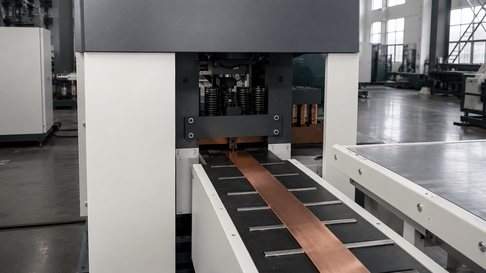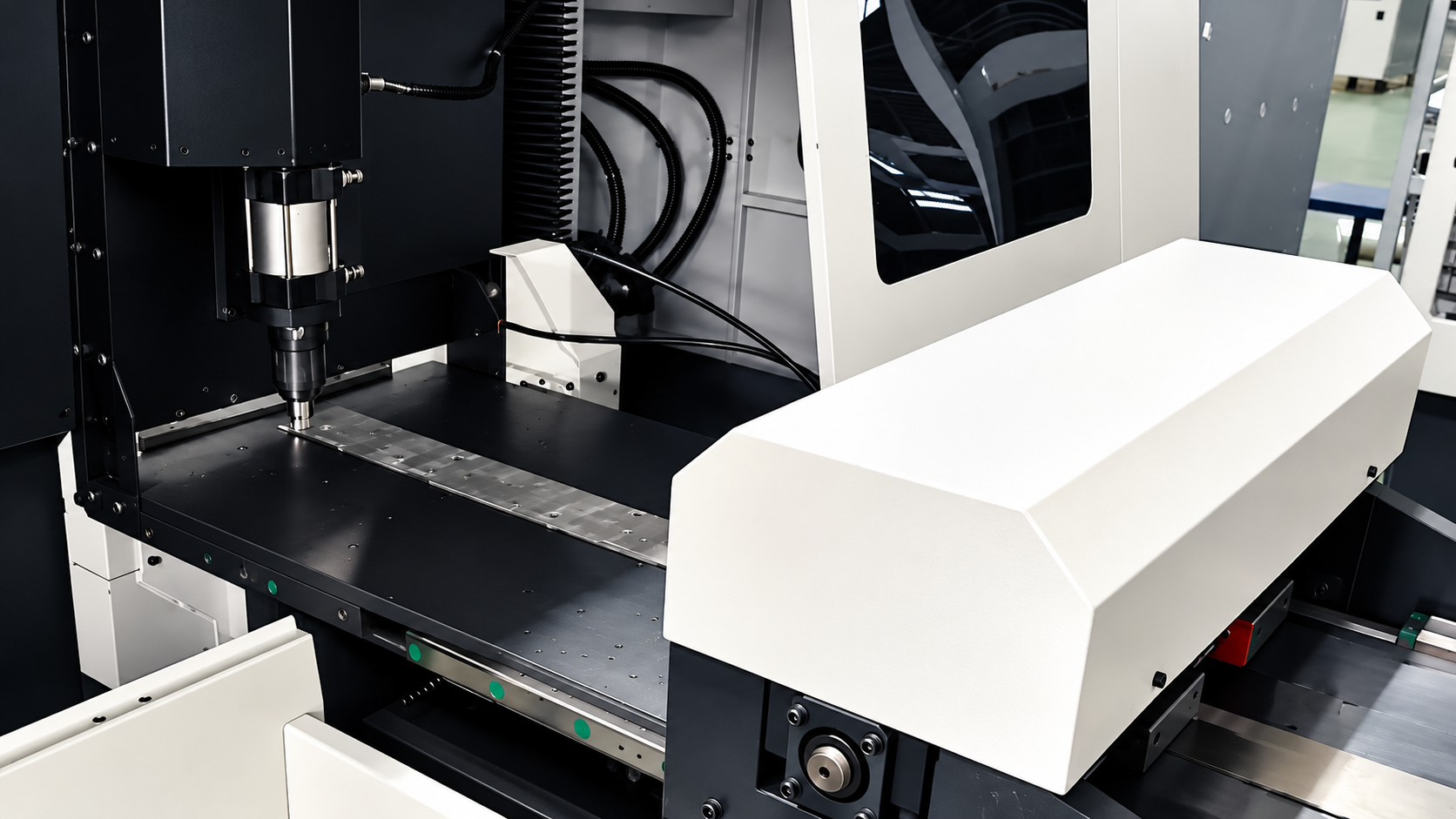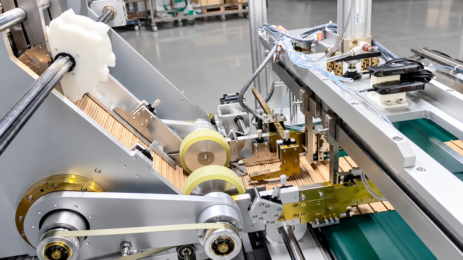
Every transformer core starts as a master coil of electrical steel — typically 1000–1250 mm wide — and almost nothing in a core shop can use it at that width. Before laminations can be cut, punched, or notched, the master coil must be divided longitudinally into narrow strips of exactly the widths each core design calls for. That is the job of the silicon steel slitting line, and it sets the quality ceiling for everything downstream: a burr or width error created here survives all the way into the finished core.
This guide explains how a silicon steel slitting line works, why burr control to ≤0.02 mm matters so much for CRGO material, and which specifications to compare when sizing a line. For the downstream process, see our transformer core cutting line guide.
What a Silicon Steel Slitting Line Does
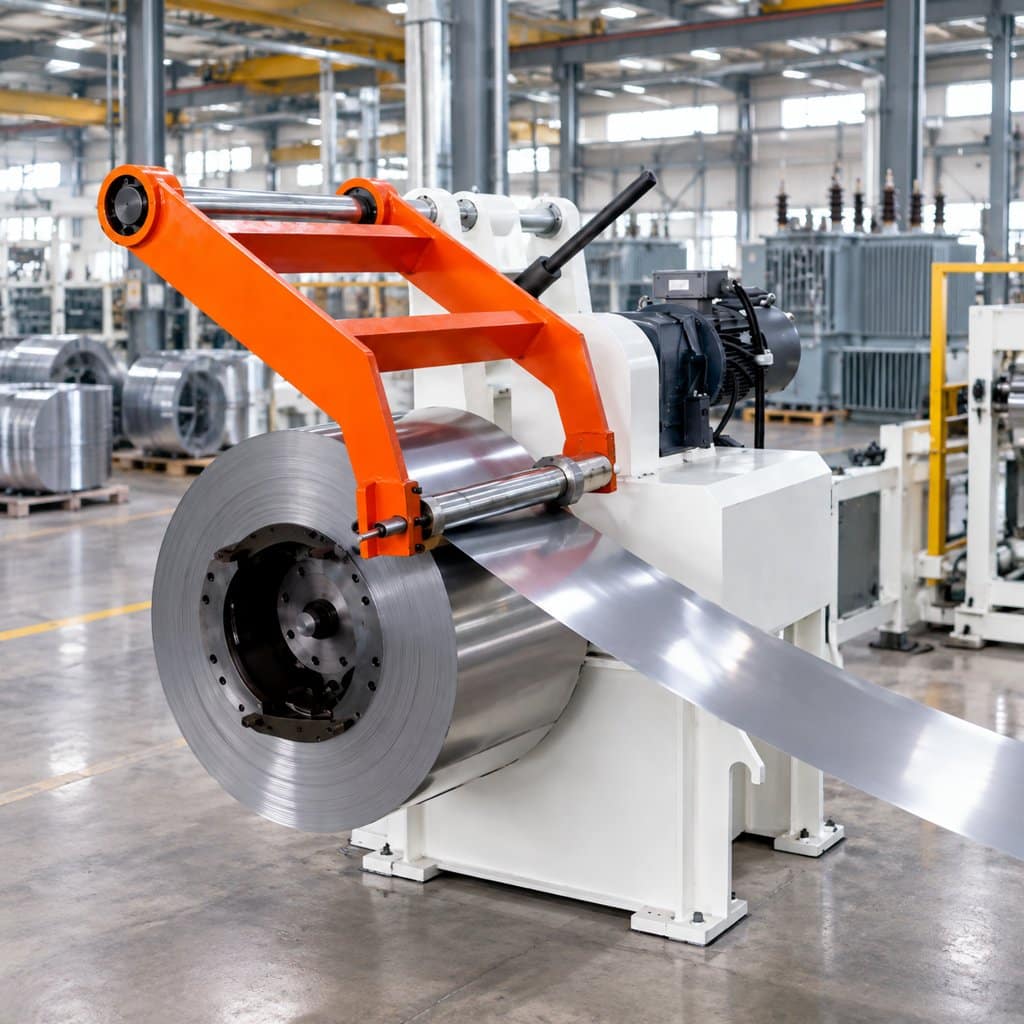
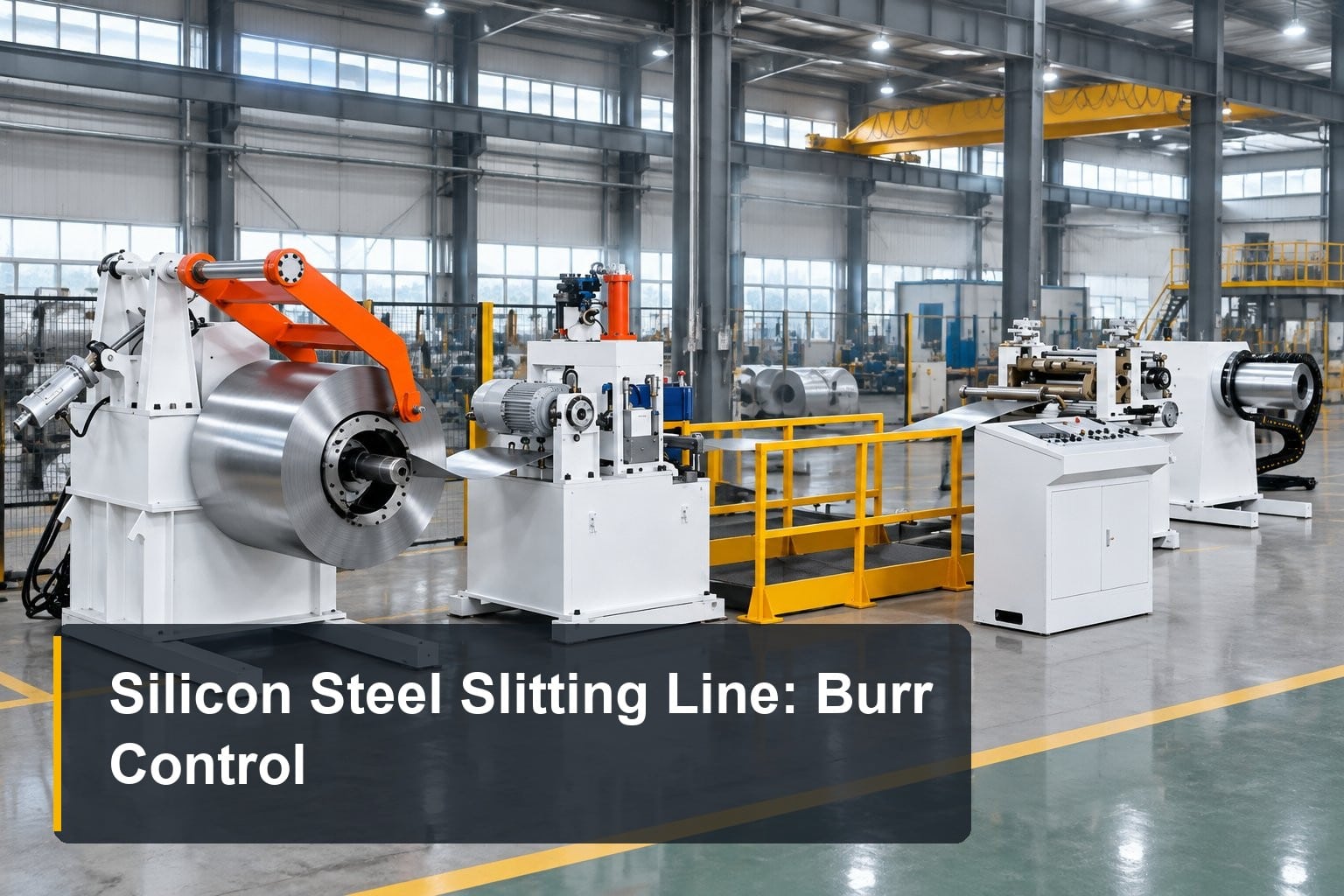
A slitting line is a longitudinal cutting system: rotary knives split a wide master coil into multiple narrower strips along the direction of material travel, and the finished strips are rewound into coils for the next process. It sits at the very front of the transformer manufacturing chain — master coil → slitting → cut-to-length or core cutting → stacking — and its output feeds every lamination the factory produces.
For transformer manufacturers, in-house slitting serves three purposes:
- Width flexibility. Different core designs need different strip widths; buying pre-slit strip locks you to a supplier’s standard widths and lead times.
- Material economics. Master coils are cheaper per kilogram than pre-slit strip, and nesting strip widths against your product mix minimizes edge trim waste.
- Quality control. Burr, camber, and edge condition are decided at the slitting knives — factories that slit in-house control the parameter that most affects core performance.
The same lines handle both CRGO (grain-oriented) strip for transformer cores and CRNGO (non-oriented) strip for motor and generator laminations, in the standard thickness range of 0.15–0.5 mm.
How the Line Works: From Master Coil to Narrow Strips
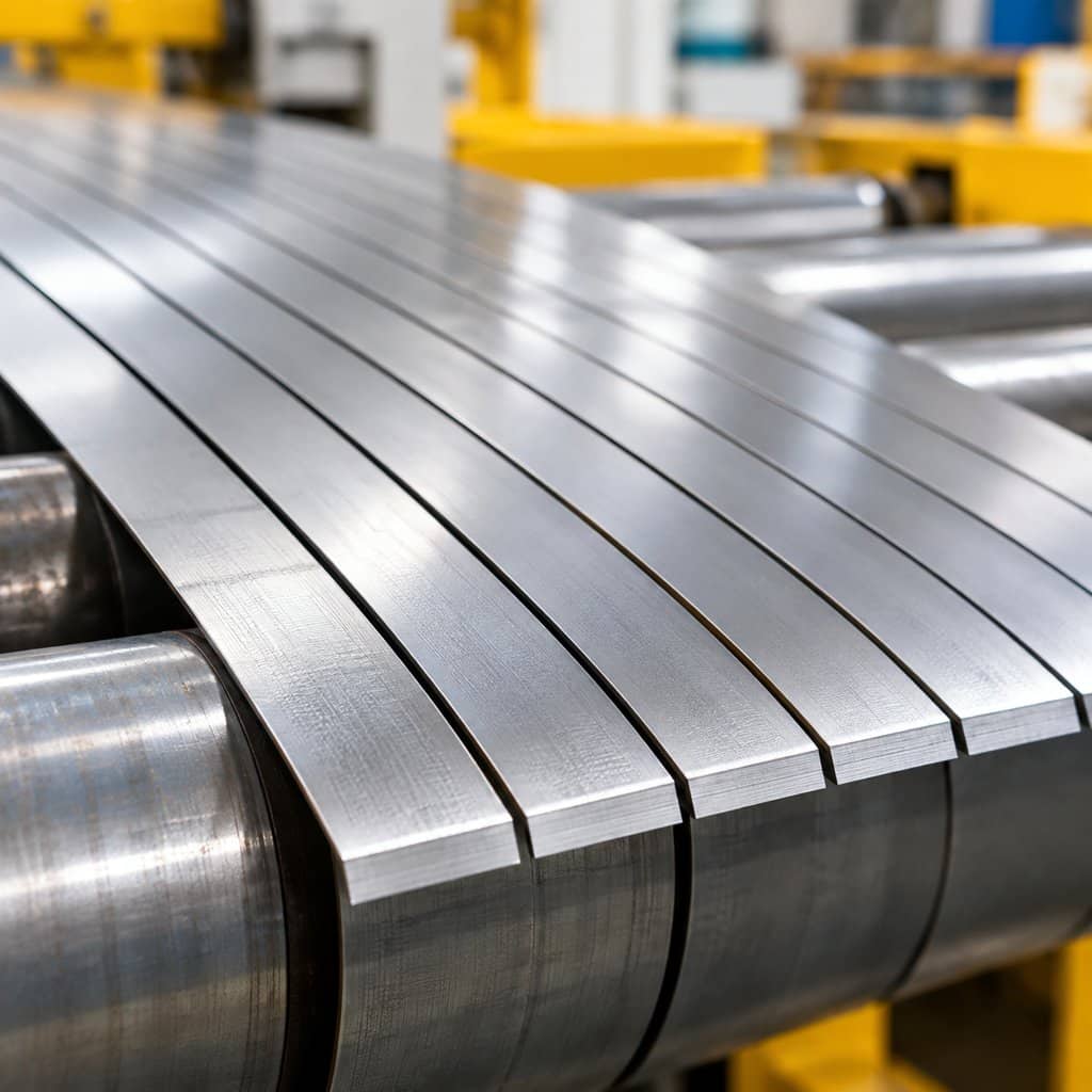
A complete slitting line is a sequence of coordinated stations, each with one job:
- Decoiling. The master coil (2T to 10T depending on line class) mounts on an expanding mandrel; a hold-down arm and peeler thread the strip head into the line.
- Pinch and leveling. Pinch rolls establish feed, and a leveler removes coil set so the strip presents flat to the knives — a precondition for uniform burr.
- Slitting head. Paired rotary knives mounted on two arbors shear the strip longitudinally. Knife setup — which widths, how many strips per pass — is the core skill of the operation. Strip widths down to 40 mm are routine on the 1250-class machines.
- Tension and loop control. A tension station (or loop pit) decouples the slitting speed from the rewinding speed so the knives see constant, stable feed.
- Recoiling. Finished strips rewind onto separate mandrels under controlled tension — too little and coils telescope, too much and thin CRGO strip stretches or edges crack.
Modern lines run at up to 120 m/min with automatic edge guiding, which is what makes high-volume slitting practical without sacrificing edge quality.
Burr Control: Why ≤0.02 mm Matters
Burr is the small rollover of metal on the cut edge, and in transformer cores it is expensive in three ways:
- Stacking factor. Burr prevents laminations from lying truly flat against each other, reducing the effective iron cross-section — the core gets bigger or the performance drops.
- Interlaminar shorts. A burr can pierce the insulating coating of the adjacent lamination, creating eddy-current paths that raise core loss and generate hot spots.
- Noise. Poorly seated laminations vibrate under magnetostriction; excessive burr shows up as audible hum in the finished transformer.
The industry benchmark for transformer-grade slitting is burr ≤0.02 mm, and holding it at 120 m/min depends on three maintenance disciplines more than on any headline spec:
- Knife clearance set as a percentage of strip thickness — too tight shaves the knives, too loose tears instead of shears.
- Knife overlap and alignment — axial runout directly becomes burr variation along the coil.
- Knife life management — CRGO coating is abrasive; disciplined regrinding intervals keep burr inside spec rather than discovering drift at the core stacking table.
When evaluating a slitting line, ask for a burr measurement report from a running machine — measured along a full coil, not at one point. We recently commissioned a line where this was the acceptance criterion: see our slitting line case study from a transformer core shop in Dhaka.
Key Specifications to Compare
The equipment family spans three coil-weight classes:
| Model | Master Coil Width | Coil Weight | Thickness | Speed | Burr | Power |
|---|---|---|---|---|---|---|
| XE-ZJX-500-3T | 100–500 mm | 2 T | 0.15–0.5 mm | 0–120 m/min | ≤0.02 mm | 26 kW |
| XE-ZJX-1250-5T | 200–1250 mm | 5 T | 0.15–0.5 mm | 0–120 m/min | ≤0.02 mm | 55 kW |
| XE-ZJX-1250-10T | 200–1250 mm | 10 T | 0.15–0.5 mm | 0–120 m/min | ≤0.02 mm | 73 kW |
Selection follows your incoming material, not the machine’s maximum: match the line class to your master coil width and weight first (the 500-class covers coils to 500 mm / 2 T; the 1250-class to 1250 mm / 5–10 T), then confirm the strip width range covers your narrowest core design. Speed matters less than buyers expect — at 0.15–0.5 mm thickness, even 60 m/min outruns most downstream cut-to-length capacity. Ready to size a machine? Follow the step-by-step sequence in our CRGO slitting line buying guide.
Slitting vs. Cut-to-Length: Different Jobs in the Same Chain
The two machines are often confused because both “cut silicon steel.” They cut in perpendicular directions and produce different things:
| Silicon Steel Slitting Line | Cut-to-Length / Core Cutting Line | |
|---|---|---|
| Cut direction | Longitudinal — splits wide coil into narrow strips | Transverse — cuts strip into individual laminations |
| Output | Narrow strip coils (rewound) | Sheets or finished core laminations |
| Key selection data | Coil width/weight, strip widths, thickness, burr, rewinding | Sheet width, cut length accuracy, punching/notching, positioning |
A factory cutting its own laminations from master coils needs both, in that order. A factory buying pre-slit strip needs only the cut-to-length side. For how that cut-to-length step works, see our silicon steel cutting machine guide; for a fuller side-by-side of the two processes, see slitting vs cut-to-length: what’s the difference.
How to Specify a Slitting Line for Quotation
Suppliers can size a line accurately if the inquiry includes:
- Master coil width range, ID/OD, and maximum coil weight
- Electrical steel grade (CRGO/CRNGO), thickness range, and coating type
- Required finished strip widths and typical number of strips per setup
- Acceptable burr and edge condition (state ≤0.02 mm explicitly if the strip feeds transformer cores)
- Rewinding tension requirements and finished coil handling method
- Workshop crane capacity, available floor space, preferred line direction, and plant electrical standard
Conclusion
A silicon steel slitting line is the upstream gatekeeper of core quality: width accuracy, edge condition, and burr ≤0.02 mm are all decided at its knives, and no downstream process can recover what slitting loses. Size the line to your master coils, treat knife clearance and regrinding discipline as part of the machine, and verify burr on a running line before you buy. For the next step in the chain, see the core cutting line guide — or send us your coil data and we’ll recommend a line class.