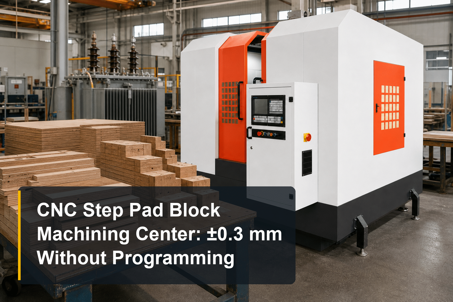
CNC Step Pad Block Machining Center: ±0.3 mm Accuracy Without CNC Programming
Step pad blocks — the stepped laminated-wood insulation components that support and clamp a transformer’s core and active part — look simple. Anyone who has machined them on a general milling machine knows otherwise: every step dimension depends on operator skill, surfaces come off burned or rough enough to need polishing, and batch consistency drifts from shift to shift. A CNC step pad block machining center exists to remove exactly these problems.
This guide explains what the machine does, how it works without conventional CNC programming, what its specifications mean for your workshop, and how to decide whether it belongs in your insulation department.
What Is a CNC Step Pad Block Machining Center?
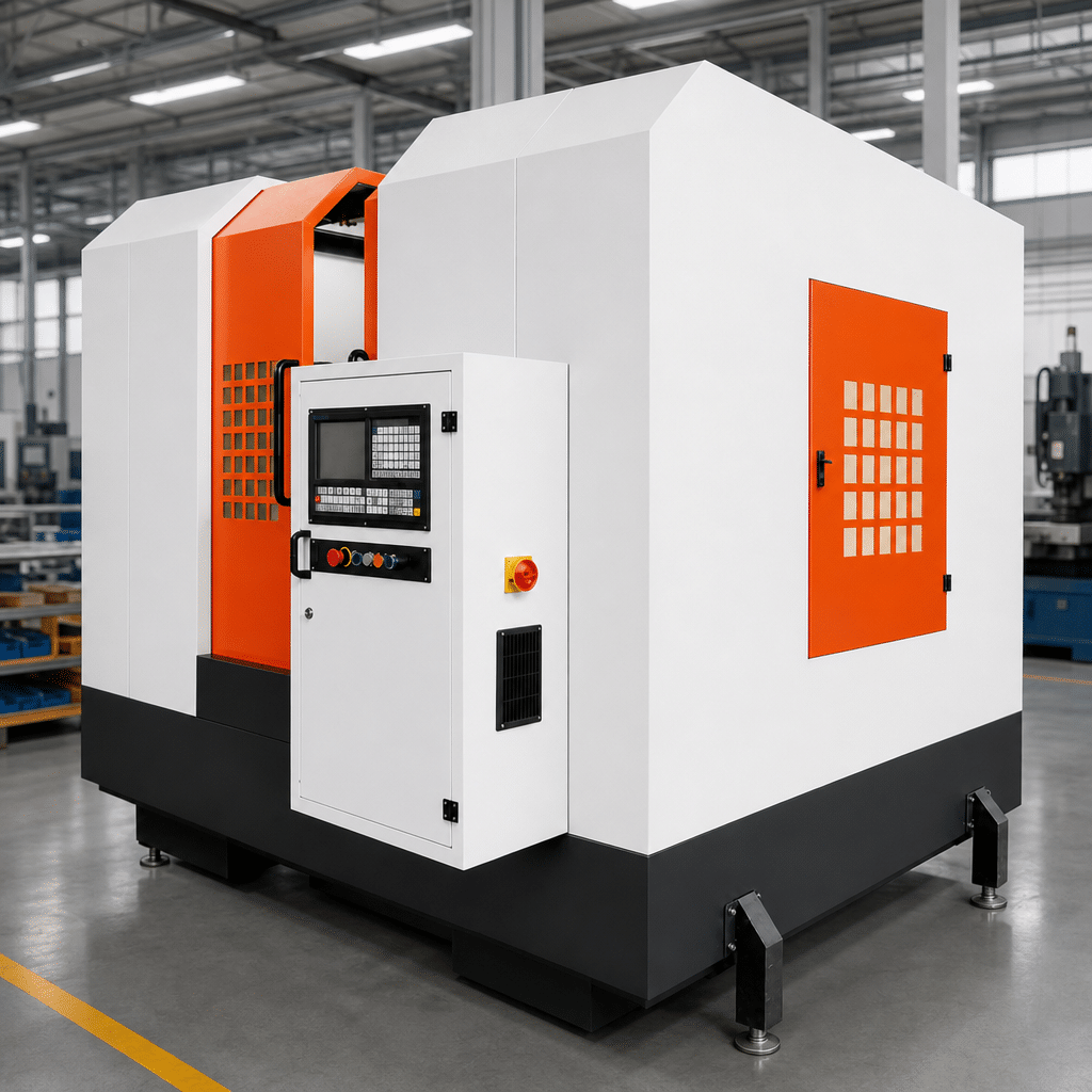
A CNC step pad block machining center — also called a CNC step-wood processing machine — is a dedicated machining system for producing stepped wooden insulation components used in transformer manufacturing. Step pad blocks are machined from laminated wood or approved transformer insulation wood, with step heights and lengths that must match the core-clamping drawing exactly, because they distribute clamping force and maintain insulation distances inside the active part.
The machine is one station in the wider transformer insulation parts processing chain. What sets it apart from the general milling machines many insulation workshops still use is its operating logic: instead of relying on manual positioning and operator experience, it converts the workpiece drawing into coordinate-based machining instructions and completes the cutting cycle automatically.
Why General Milling Machines Struggle with Step-Wood
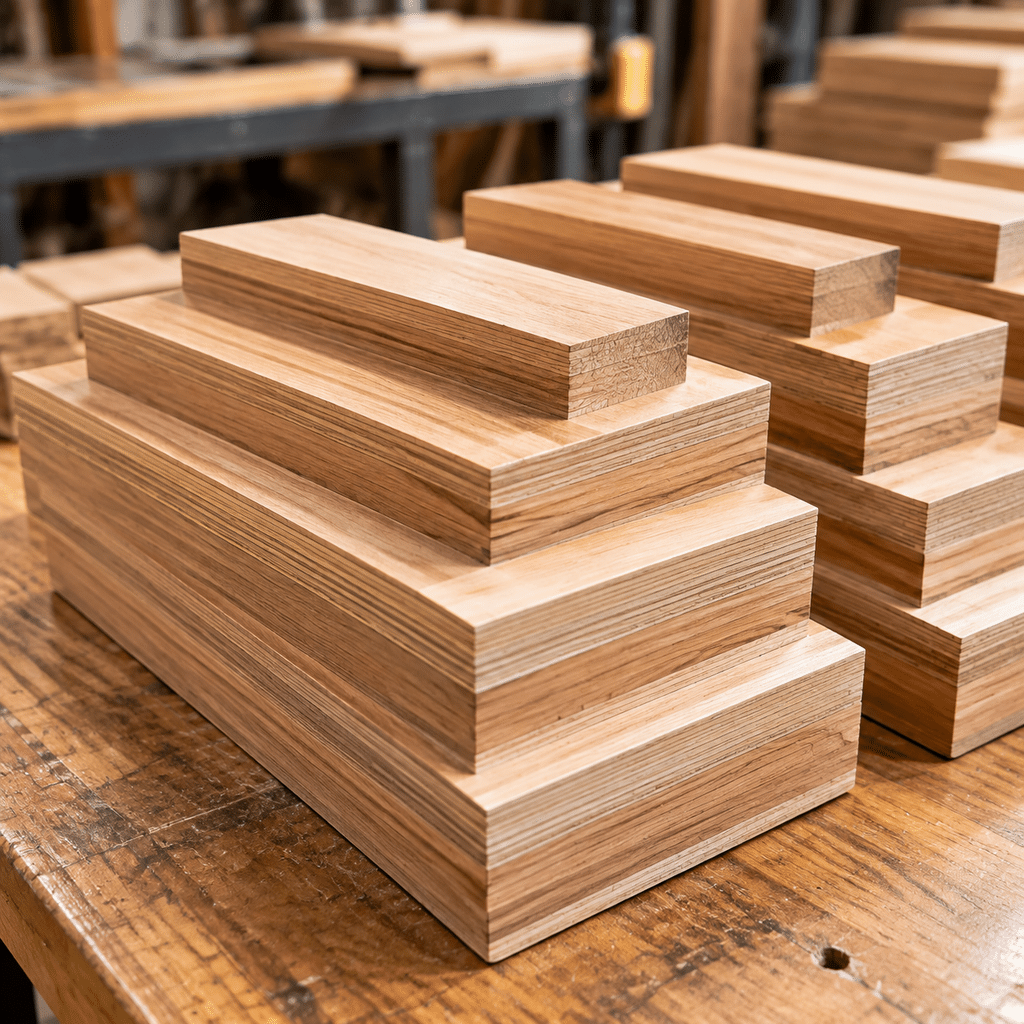
General-purpose milling can produce step blocks — slowly, and inconsistently. The typical pain points in a transformer insulation workshop:
- Operator dependence. Step dimensions are set by manual positioning. Quality follows the operator, not the drawing — a problem when your best miller is absent or leaves.
- A hidden second operation. Conventional milling often leaves surfaces rough or slightly carbonized, so parts go through a separate polishing or sanding step before they can move to assembly. That is extra labor, extra handling, and extra lead time that rarely appears in cost calculations.
- Batch drift. Manual setup means the first part and the fiftieth part are not identical, which shows up later as fitting problems during active-part assembly.
For suitable workpieces, a dedicated machining center runs at at least three times the efficiency of ordinary milling-machine processing — and the finished surface can go directly to the next production stage without polishing when it meets the drawing and inspection requirements.
How It Works: Coordinates In, Finished Part Out
The operating cycle is deliberately simple:
1. Input coordinates, not code. The operator reads the approved drawing and enters the machining coordinates on a visual control interface. There is no G-code programming and no CAM software — which is what “no programming required” means in practice. Setup for a new part is measured in minutes, and repeat jobs are recalled, not re-learned.
2. Automatic machining cycle. Once coordinates are entered, the machine completes the step profile automatically. A professional woodworking saw blade running at 2,800 rpm cuts the laminated wood without burning or carbonizing the surface under the specified process conditions.
3. Matched feed speed. Feed is steplessly adjustable from 0–5 m/min, so the cutting speed can be tuned to the material, the step geometry, and the surface quality required — slower for a fine finish, faster for roughing or softer stock.
The practical result: machining quality stops depending on who is standing at the machine, and starts depending on the drawing.
Key Specifications
The CNC step-wood processing machine is built around a compact, foundation-free installation:
| Parameter | Specification |
|---|---|
| Milling blade speed | 2,800 rpm |
| Feed speed | 0–5 m/min, stepless adjustment |
| Machining accuracy | ±0.3 mm |
| Total power | 11 kW (excluding dust collector) |
| Maximum step-wood size | 500 mm (W) × 500 mm (H) × 600 mm (L) |
| Customized size | Available according to approved workpiece requirements |
Two practical notes on this table. First, no dedicated foundation is required — the machine can be positioned according to your insulation workshop layout, subject to normal leveling, power, and dust-collection requirements. Second, if your step blocks exceed the standard 500 × 500 × 600 mm envelope, the workpiece range can be customized after review of your drawings.
What ±0.3 mm Accuracy Means for Transformer Assembly
Buyers sometimes compare this figure against metal-cutting machining centers and ask whether ±0.3 mm is “tight enough.” For laminated-wood insulation components, it is the right target, for three reasons:
- Wood behaves differently from steel. Laminated wood compresses slightly under clamping force; sub-0.1 mm metalworking tolerances buy nothing in the assembled core.
- Consistency matters more than the number. Every sampled step height, position, and length holding within ±0.3 mm across a batch is what keeps active-part assembly predictable.
- Surface quality is the real differentiator. A smooth, non-carbonized surface that passes inspection without polishing saves a full operation on every part — worth more in labor than chasing a tighter tolerance on paper.
Field results confirm the point. At a transformer manufacturer in Warsaw, Poland, a CNC step-wood processing machine held every sampled dimension within ±0.3 mm, and the machined surfaces passed inspection directly — the sanding operation was dropped from the production route entirely.
Who Should Invest — and How to Specify for a Quotation
The machine makes sense when step pad blocks are a recurring part of your production, not an occasional one-off:
- Transformer insulation workshops currently machining step blocks on general milling machines, where labor and polishing eat the margin
- Batch producers who need repeated coordinates and consistent step geometry across shifts
- Factories with custom designs — step blocks produced to customer drawings, where fast coordinate setup shortens the lead time per variant
Just as important is who should not buy one yet: if step blocks are an occasional one-off rather than a recurring part family, outsourcing or general milling remains cheaper — dedicated equipment earns its floor space only when the batch volume is there.
If your parts are mostly flat pressboard components rather than stepped wooden blocks, a different machine fits better — an insulation parts processing center handles milling, drilling, and slotting of flat parts, as one installation in Nairobi, Kenya shows.
When you are ready to request a quotation, prepare the information suppliers actually need: workpiece drawings, material details, maximum dimensions, required accuracy, production volume, power supply, and dust-collection requirements. A serious supplier will review your step-block drawings before recommending a standard or customized envelope — and a test cut on your own material is the most honest accuracy demonstration you can ask for.
Have step pad block drawings on hand? Send them with your target output, and we will confirm whether the standard 500 × 500 × 600 mm envelope fits, or spec a customized machine that does.