| Equipment | CNC Busbar Connection Processing Line (200 kN nominal pressure, 5 × 160 mm processing range) |
| Customer | Busbar trunking and low-voltage switchgear manufacturer in Manila, the Philippines |
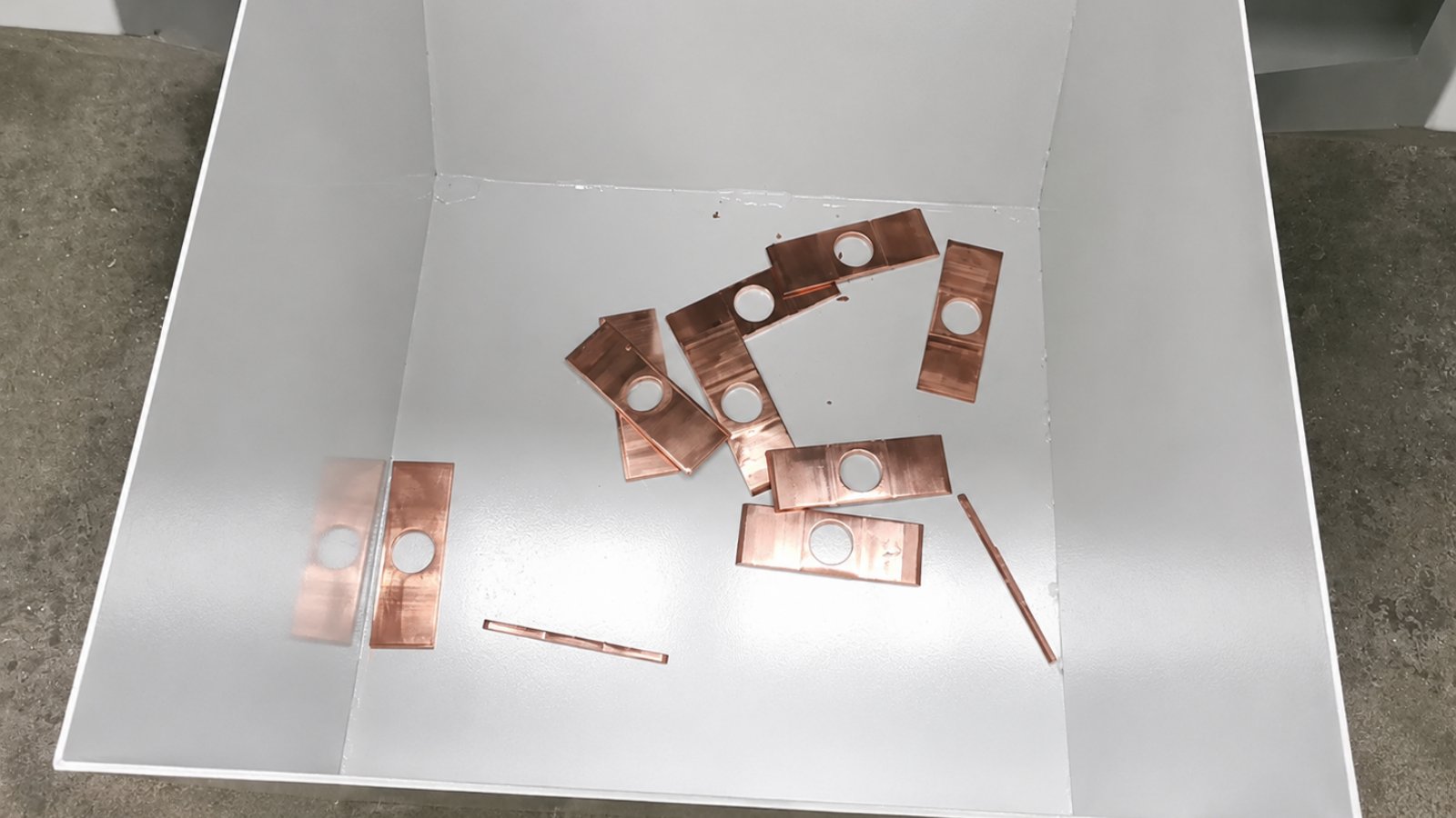
| Application | Punching, drawing, embossing and shearing of copper busbar connection bars in one clamping |
Customer information has been anonymized. Technical figures are design and acceptance reference values and may vary depending on configuration and site conditions.
A busbar trunking and low-voltage switchgear manufacturer in Manila used to make its connection bars on three separate machines: a punching machine for the holes, a shear for cutting to length, and embossing either subcontracted or tapped out by hand. As soon as order quantities came up, hole spacing and embossed positions began to drift, and the assembly line ended up reaming holes to make parts fit.
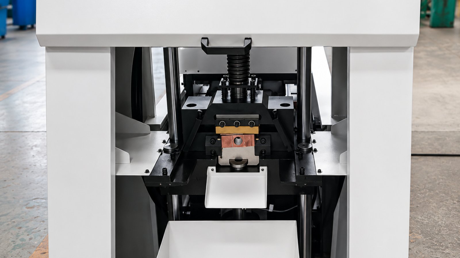
Tranfovia built a CNC busbar connection processing line around the customer’s connection-bar drawings: 200 kN nominal pressure, a 5 × 160 mm processing range, one-time clamping with automatic clamp switching under program control, and punching, drawing, embossing and shearing completed on the same line.
1. Customer Background
The customer supplies busbar trunking and low-voltage assemblies to data centre and industrial plant projects in the Philippines and across Southeast Asia, and runs its own copper bar workshop in the plant.
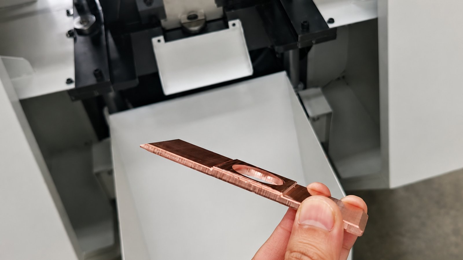
A connection bar is the transition piece between two trunking sections, or between a busbar and a breaker terminal. A single part usually carries one or two holes and one embossed or drawn step, with length and hole pitch set by the project drawing. The difficulty is variety: one project may need several hundred to over a thousand pieces spread across a dozen different connection-bar variants.
The workshop used to split the work across three machines. Holes were punched on a punching machine, length was cut on a shear, and embossing and drawing were either sent out or formed in a bench vice. Three operations meant three clampings and three fresh datums.
2. Industry Pain Points
1. Three clampings mean three datums. Punching, shearing and embossing on three machines force the operator to re-establish the datum each time, so hole position error accumulates along the route and parts no longer line up at the panel.
2. Thin, long bars move during punching. A bar that is not held firmly kicks back the moment the punch bites, and hole position follows it; the operator compensates with a stop gauge and feel, which puts consistency in human hands.
3. Embossing and drawing are hard to hold. The embossed step on a lap joint governs how well two bars seat and carry current, and hand-formed steps vary in depth from part to part within the same batch.
4. Changeover means stripping the tooling. With a dozen variants in rotation, every change needs a die change, alignment and a first-article check, and the parts waiting for them are usually on the assembly line.
5. Skilled operators are getting scarce. People who can read the drawing, set the tooling and judge embossing depth are hard to hire, and new operators take a long time to reach rate.
3. Solution
3.1 One clamping with automatic clamp switching
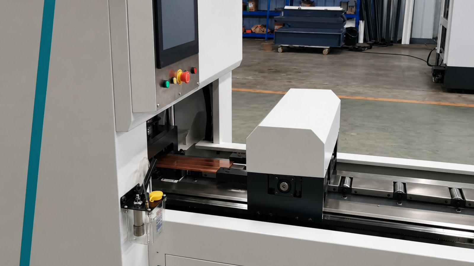
Raw material enters from a single initial clamping position. From there the program switches the clamping position repeatedly as the process advances, so the bar is never unloaded and re-datumed between operations.
3.2 200 kN hydraulic punching head
The main punching head is hydraulically driven: 200 kN nominal pressure, 30 mm cylinder stroke and 60 strokes per minute. Hole position comes from the X axis at up to 50 m/min positioning speed, so pitch is set by the program rather than by a stop gauge.
3.3 Hydraulic copper bar clamping
The clamping system holds force through punching, drawing, embossing and shearing, suppressing movement in thin, long bars and holding hole-spacing accuracy at ≤ ±0.2 mm.
3.4 Touch-screen parameter entry
Hole pitch, hole count, finished length and operation sequence are entered on the HMI. The servo system drives through a ball screw and linear guide rail, so positioning is completed by the axis instead of by an operator pushing material into a stop.
3.5 Sizing that covers common connection bars
The 5 × 160 mm processing range takes copper bar up to 5 mm thick and 160 mm wide through punching, drawing, embossing and shearing in one pass. Total power is 6 kW.
3.6 Footprint and installation
The machine measures 5600 × 1066 × 1530 mm and weighs 1300 kg, so it can stand beside existing busbar equipment instead of taking a dedicated bay.
4. Implementation and Commissioning
Step 1: Dies and operation sequence fixed against the drawing. The customer supplied connection-bar drawings with material, section, hole pattern, embossing or drawing features, finished length and batch size, and both sides agreed the order of the four operations and the tooling set.
Step 2: Trial punching and first-article approval. Axis motion and clamp switching were checked on a dry run, then single parts were formed to the actual drawing and measured for hole pitch, embossed step depth and sheared face quality.
Step 3: Installation and connection. The 1300 kg machine was set in place, levelled and anchored, then connected to the 6 kW supply, the hydraulic unit and earth, with HMI parameters and axis limits verified.
Step 4: Pilot batch and parameter freeze. A pilot batch ran at the 60 strokes per minute punching frequency with hole pitch sampled against ≤ ±0.2 mm, and the pitch, hole count and sequence for each variant were frozen into a process card that operators call up on screen.
5. Acceptance Results
| Item | Design and acceptance reference |
| Model | MX.JCX-130 |
| Nominal pressure | 200 kN |
| Maximum X-axis positioning speed | 50 m/min |
| Punching cylinder stroke | 30 mm |
| Punching frequency | 60 times/min |
| Hole distance control accuracy | ≤ ±0.2 mm |
| Processing range | 5 × 160 mm |
| Total power | 6 kW |
| Overall dimensions | 5600 × 1066 × 1530 mm |
| Gross weight | 1300 kg |
6. Customer Feedback
“Hole spacing used to be walked across three machines one at a time. Now the bar goes in, the program runs, and what comes out is already punched and embossed. We sample at ±0.2 mm and it holds.” — Equipment manager
“Changeover went from stripping dies and re-aligning to editing parameters on the screen, so new operators get to rate far faster. Embossing no longer goes out to a subcontractor, and our schedule is no longer held up in someone else’s workshop.” — Production manager
7. Summary and Next Steps
Choosing equipment for connection bars is not only a question of nominal pressure. What decides whether a connection bar is made in one pass is whether the machine can hold a thin, long copper bar, who defines the hole position, whether embossing and drawing share the datum with the holes, and whether a variant change means stripping the tooling. This line combines one-time clamping with automatic clamp switching, a 200 kN hydraulic punching head, hydraulic clamping and touch-screen parameter entry in one machine. Next, the customer is entering the pitch and operation sequence for all of its connection-bar variants into the program and folding the sampling records into the quality file for each trunking run.
- WhatsApp: +86-15958243831
- Email: sales@tranfovia.com
- Website: https://tranfovia.com/