TL;DR:
- A transformer core cut-to-length line with center positioning cuts silicon steel laminations to length while referencing the sheet’s centerline, keeping both edges symmetrical.
- The two specifications that matter most are cutting accuracy (length tolerance and burr height) and the positioning method (mechanical, servo, or vision-based).
- Match the model to your lamination width range, material grade, and daily output — not to the headline speed alone.
- Before buying, verify accuracy claims with on-site test cuts, confirm after-sales support, and check the supplier’s transformer-industry references.
How to choose the right transformer core cut-to-length line (center positioning) comes down to understanding the machine, comparing the specifications that actually affect core quality, and verifying the supplier before you sign. This article explores what the machine does, which specifications to compare, how to match a model to your application, and the questions to ask any manufacturer or supplier, providing a practical buying framework for transformer producers.
What a Transformer Core Cut-to-Length Line (Center Positioning) Is
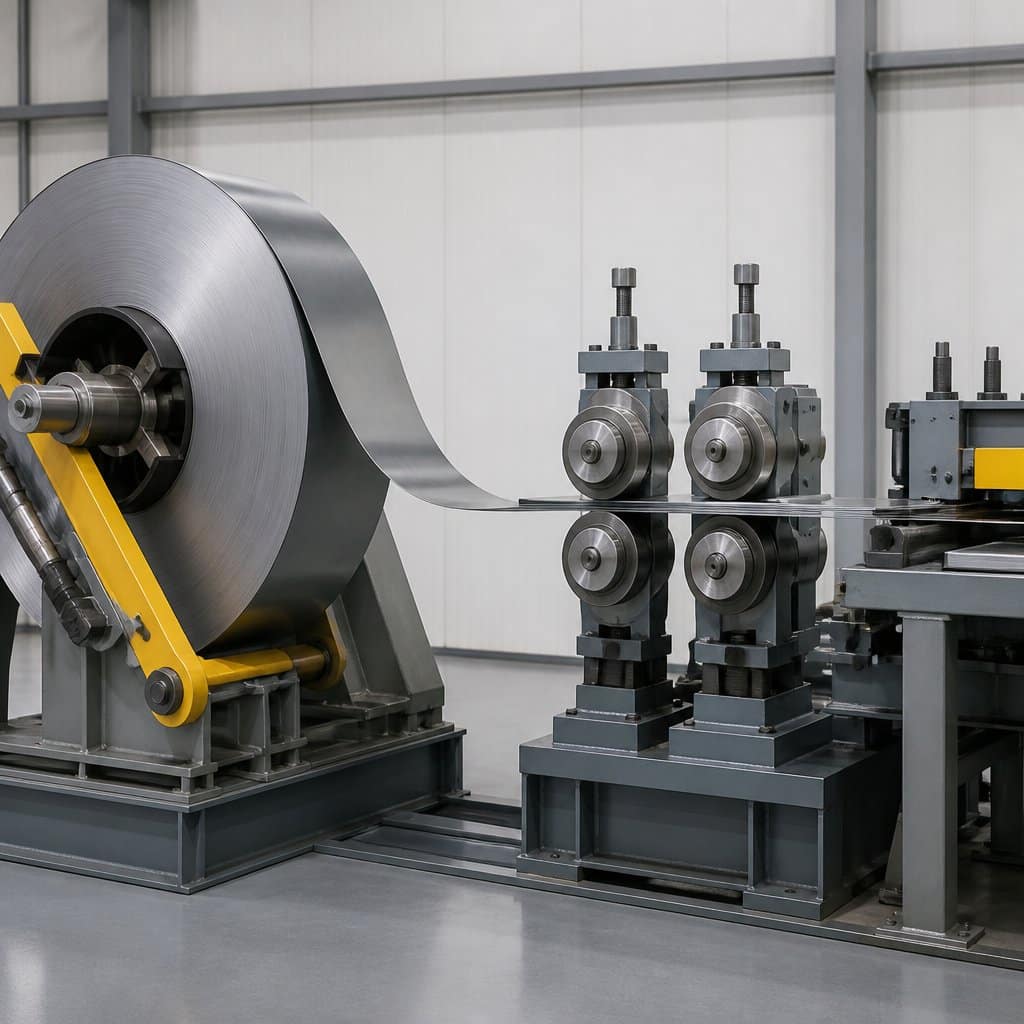
A center-positioning cut-to-length line is the machine that turns slit silicon steel strip into finished core laminations of precise length. Understanding its role in the production flow clarifies why positioning accuracy has an outsized effect on the finished transformer core.
Definition and Core Function
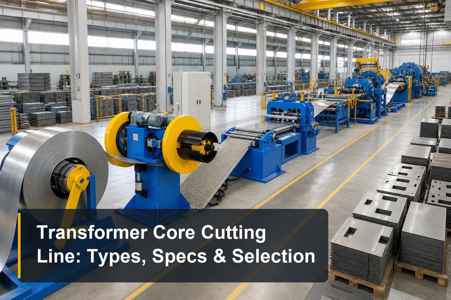
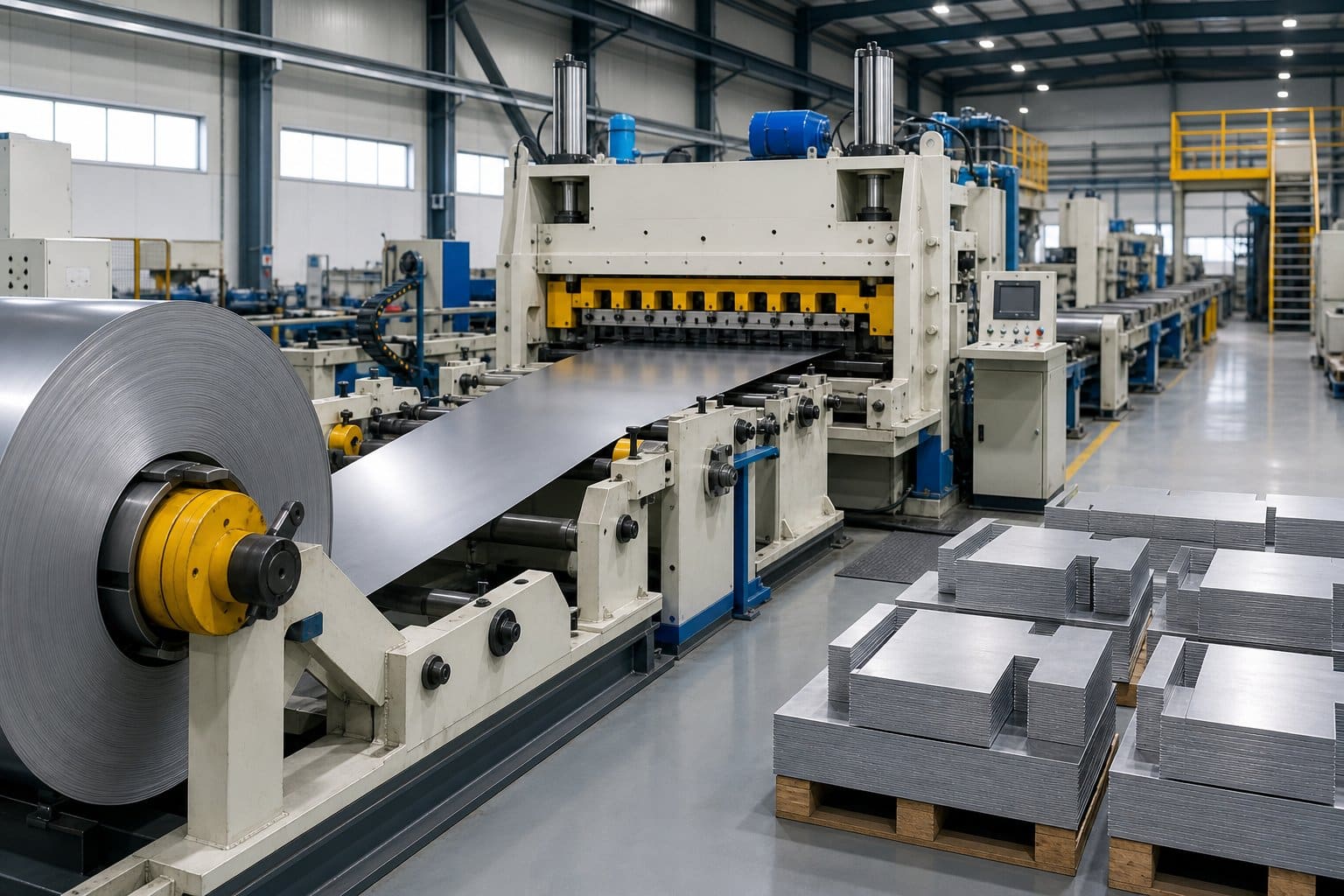
In simple terms, a transformer core cut-to-length line (center positioning) uncoils or feeds silicon steel strip, positions it against the sheet’s centerline, and shears or punches it into laminations of a programmed length. Center positioning means the machine aligns the strip by its middle axis rather than one edge, so any width variation is distributed symmetrically on both sides. This keeps yoke and leg laminations balanced, which directly improves core stacking quality and reduces assembly rework later in production.
Where It Fits in Transformer Manufacturing
The line sits between slitting and core stacking in the production flow. Wide electrical steel coils are first reduced to working width on a silicon steel slitting line, and the cut-to-length line then converts that strip into individual laminations with the required lengths, notches, and punch holes. Because every downstream process — stacking, clamping, and core-coil assembly — inherits the geometry of these laminations, errors made here cannot be corrected later. That is why experienced buyers treat this machine as a quality-critical asset rather than a simple shear.
Center Positioning vs. Other Layouts
Cut-to-length lines are built around three positioning philosophies: edge positioning, center positioning, and center-piece (V-notching) arrangements. Edge positioning references one side of the strip and suits simple rectangular laminations, while center positioning suits symmetrical EI and step-lap cores where both edges must stay balanced. Center-piece designs integrate additional notching for special core geometries. Choosing between them is a core-design decision first and a machine decision second, which is why the specification review below starts with positioning method.
Key Specifications to Compare
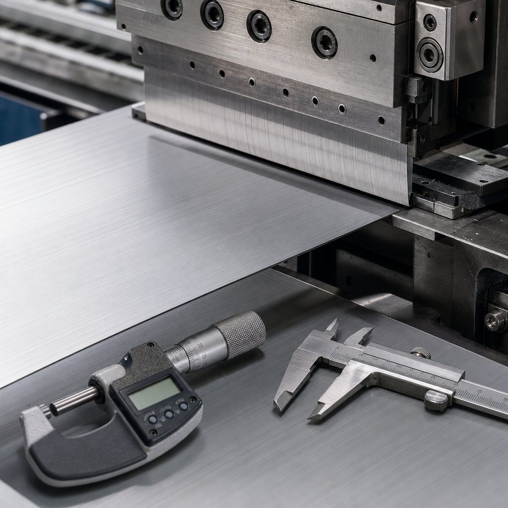
Brochures list dozens of parameters, but only a few determine whether a transformer core cut-to-length line (center positioning) will hold tolerance shift after shift. Focus your comparison on cutting accuracy, positioning method, and realistic throughput for your sheet sizes.
Cutting Accuracy and Burr Height
Length tolerance is the headline figure: quality lines hold ±0.1 mm to ±0.2 mm on lamination length, with angle accuracy around ±0.05° on mitered cuts. Equally important is burr height, which should stay below roughly 0.02 mm on grain-oriented silicon steel. Excessive burr short-circuits adjacent laminations in the stacked core, raising eddy-current losses and no-load current. Ask every supplier to state both figures as guaranteed values under production conditions, not laboratory bests, and request the measurement method behind each claim.
Positioning Method and Repeatability
Center positioning systems range from mechanical centering guides to servo-driven grippers with encoder feedback and, at the top end, vision-based alignment. What matters is repeatability: the centerline deviation should stay within ±0.1 mm across the full width range. Servo systems compensate for strip camber and width variation automatically, which mechanical guides cannot. If your product mix also includes asymmetrical laminations, compare how the machine handles edge-referenced jobs — a side-position core cutting line may complement or replace a center-positioning model for those designs.
Speed, Width Range, and Automation Level
Rated feeding speed — often 60 to 240 m/min — means little without context. Effective output depends on acceleration, cut cycle time, and how quickly the line changes between lamination lengths. Check the supported strip width range (commonly 40–1000 mm) and thickness range (0.18–0.5 mm for grain-oriented steel) against your core drawings. CNC recipe storage, automatic tool adjustment, and integration with stacking or sorting units reduce changeover from hours to minutes, which matters more than peak speed for high-mix production.
Matching the Right Model to Your Application
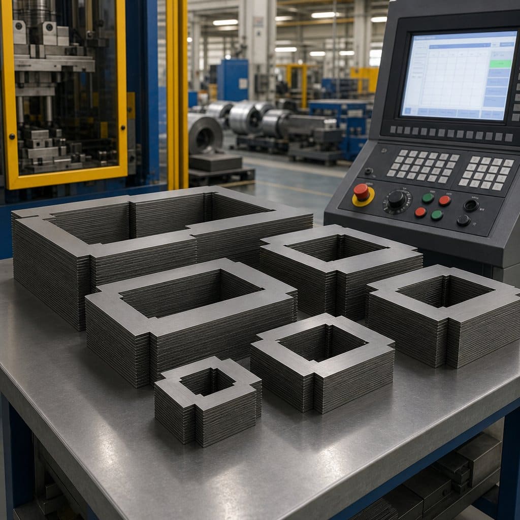
The right transformer core cut-to-length line (center positioning) is the one whose working envelope matches your core designs and whose capacity matches your real production plan. Three factors drive that match: lamination geometry, volume, and material.
Lamination Size and Core Design
Start from your core drawings, not from the machine catalog. List the minimum and maximum lamination widths and lengths you cut today and expect to cut within five years, including step-lap patterns and miter angles. A distribution transformer shop cutting small EI laminations has very different needs from a power transformer plant cutting meter-long step-lap sheets. Buying a line whose width or length range barely covers your largest core leaves no margin for new designs; buying far beyond your range adds cost and often sacrifices accuracy at the small end.
Production Volume and Shift Pattern
Match capacity to your realistic output, not your optimistic forecast. Estimate laminations per shift by core type, then add changeover frequency — a high-mix shop cutting twenty core designs needs fast recipe changeover more than maximum feeding speed. Single-shift operations can often justify a mid-range line with manual tool adjustment, while two- or three-shift plants should invest in servo positioning, automatic tool setting, and sorting automation to keep accuracy stable across long runs and operator changes.
Material Grade and Thickness
Confirm the line is built for your steel. Grain-oriented silicon steel between 0.18 mm and 0.35 mm demands sharp, precisely gapped shear blades and gentle handling to avoid stress that degrades magnetic properties. If you also process non-oriented steel or thicker grades, verify the shear gap adjustment range and blade material. A machine optimized only for thin high-grade strip may burr or deform thicker material, so ask for test cuts on your actual steel grades before finalizing the specification.
Questions to Ask the Manufacturer or Supplier
A transformer core cut-to-length line (center positioning) is a ten-to-twenty-year asset, so supplier quality matters as much as machine quality. Use these questions to separate experienced transformer equipment specialists from general machinery traders.
How Will You Verify the Accuracy Claims?
Ask for a factory acceptance test on your own material: the supplier should cut a defined batch of your laminations and provide measured length, angle, and burr data. Reputable manufacturers welcome this and will demonstrate the machine running your longest and shortest designs. When reviewing a specific model such as a center-position core cutting line, request the positioning repeatability data across the full width range, plus contactable references from transformer factories running the same model on similar core designs.
What After-Sales Support Do You Provide?
Clarify installation, commissioning, and operator training scope in writing before purchase. Ask how quickly wear parts — shear blades, guides, encoders — ship, whether remote diagnostics are supported, and who performs the first-year maintenance. A supplier that offers pre-shipment inspection, documented spare-parts lists, and responsive technical support will cost less over the machine’s life than a cheaper quote with vague service terms. Response time commitments matter most in the first months of production ramp-up.
Can You Support Turnkey Integration?
Few factories buy a cut-to-length line in isolation. Ask whether the supplier can integrate decoilers, stacking tables, and sorting units into a coordinated cell, and whether they understand the full transformer process from slitting to core assembly. Suppliers with genuine transformer process know-how can advise on lamination design, step-lap patterns, and line layout — value that a pure equipment seller cannot offer. This integration capability is often the strongest predictor of a smooth commissioning and a fast return on investment.
Frequently Asked Questions
What is center positioning on a cut-to-length line?
Center positioning aligns the silicon steel strip by its centerline rather than one edge before cutting. Any strip width variation is then distributed symmetrically on both edges, keeping laminations balanced. This is the preferred method for symmetrical EI and step-lap cores, where edge-referenced cutting would shift the lamination geometry and complicate stacking.
What cutting accuracy should I expect?
A quality transformer core cut-to-length line (center positioning) holds lamination length tolerance around ±0.1–0.2 mm and burr height below about 0.02 mm on grain-oriented silicon steel. Treat these as production-condition guarantees to be verified by test cuts on your material, not brochure figures achieved under ideal laboratory settings.
Center positioning or side positioning — which do I need?
Choose center positioning when your cores are symmetrical designs such as EI and step-lap laminations, because it keeps both edges balanced. Choose side (edge) positioning for asymmetrical shapes or when one edge must serve as the datum. Many factories run both types, or select a configurable line, depending on their core design mix.
How much does a center-positioning cut-to-length line cost?
Price depends on width range, positioning system (mechanical, servo, or vision-based), automation level, and integrated punching or sorting options. Servo-driven CNC lines with automatic tool setting cost more upfront but repay through faster changeover and stable accuracy in high-mix production. Request itemized quotations matched to your core drawings rather than comparing headline prices.
Summary
Choosing the right transformer core cut-to-length line (center positioning) is a structured decision: understand how the machine fits your production flow, compare cutting accuracy and positioning repeatability rather than headline speed, match the working envelope to your core designs and volume, and verify the supplier through test cuts, references, and clear after-sales terms. Buyers who follow this sequence consistently end up with lines that hold tolerance for years.
For expert guidance on selecting a cut-to-length line or a complete transformer production line, contact TRANFOVIA today.
📞 +86-15958243831 📧 sales@tranfovia.com 💬 WhatsApp: https://wa.me/8615958243831 🌐 tranfovia.com
References
- IEC 60076-1:2011. Power transformers — Part 1: General. International Electrotechnical Commission. https://webstore.iec.ch
- IEEE Std C57.12.00-2015. IEEE Standard for General Requirements for Liquid-Immersed Distribution, Power, and Regulating Transformers. IEEE. https://standards.ieee.org
- ASTM A876/A876M. Standard Specification for Flat-Rolled, Grain-Oriented, Silicon-Iron, Electrical Steel. ASTM International. https://www.astm.org
- Kulkarni, S. V., & Khaparde, S. A. (2004). Transformer Engineering: Design and Practice. Marcel Dekker.
- Georgilakis, P. S. (2009). Spotlight on Modern Transformer Design. Springer.
- U.S. Department of Energy. Distribution Transformer Efficiency and Core Loss Reduction. https://www.energy.gov