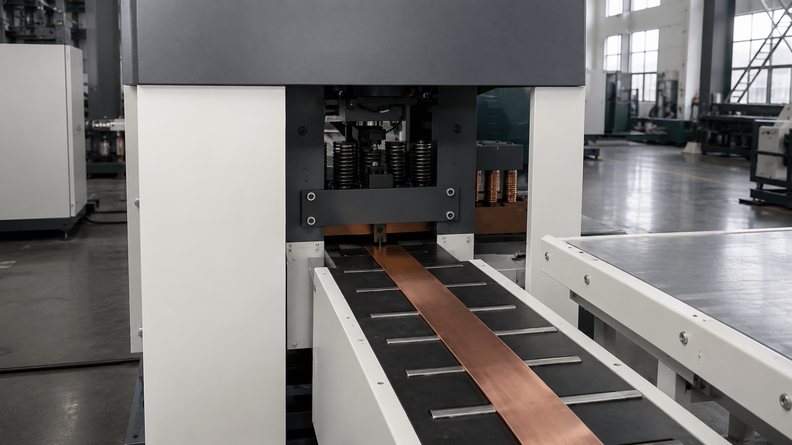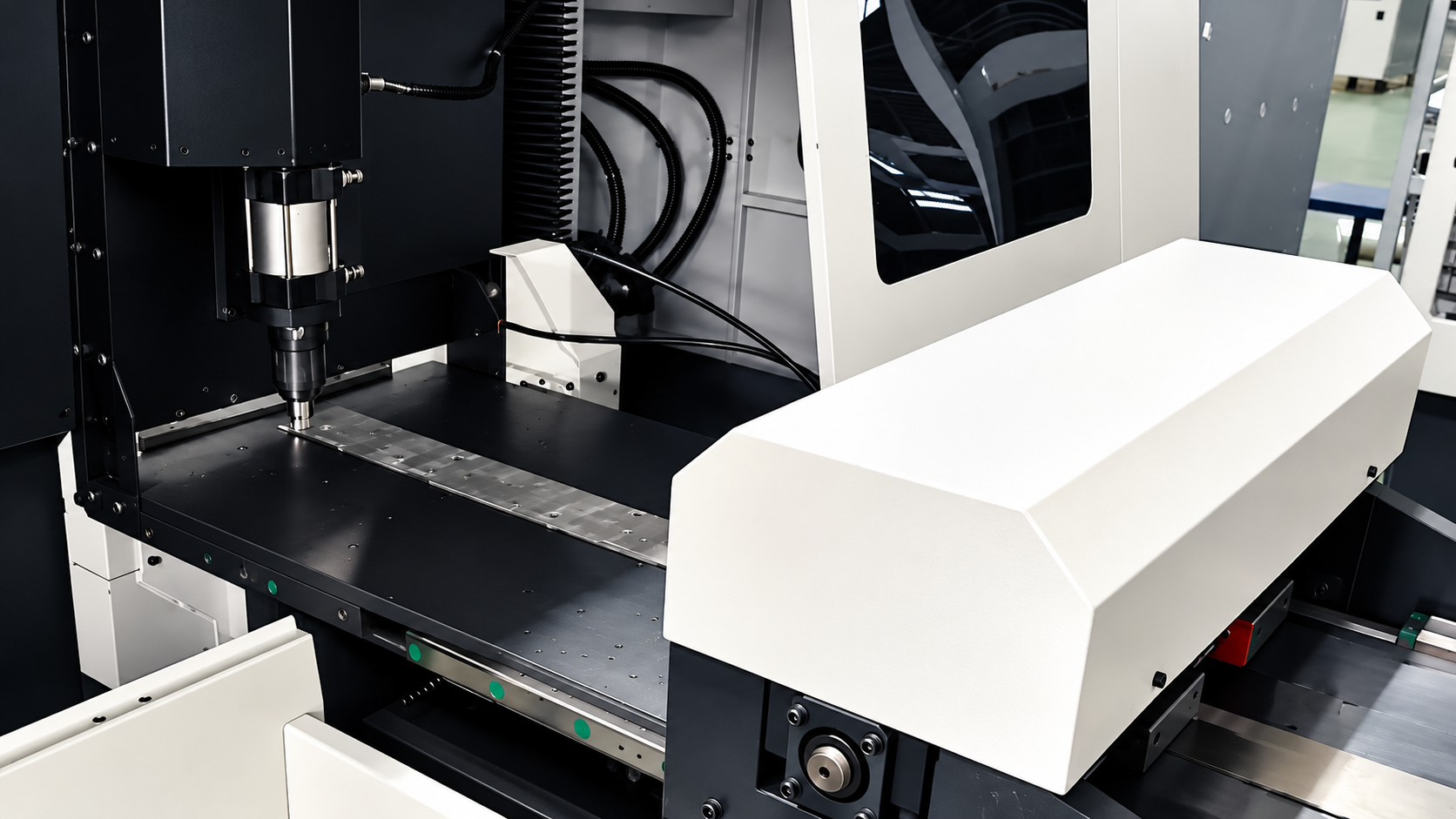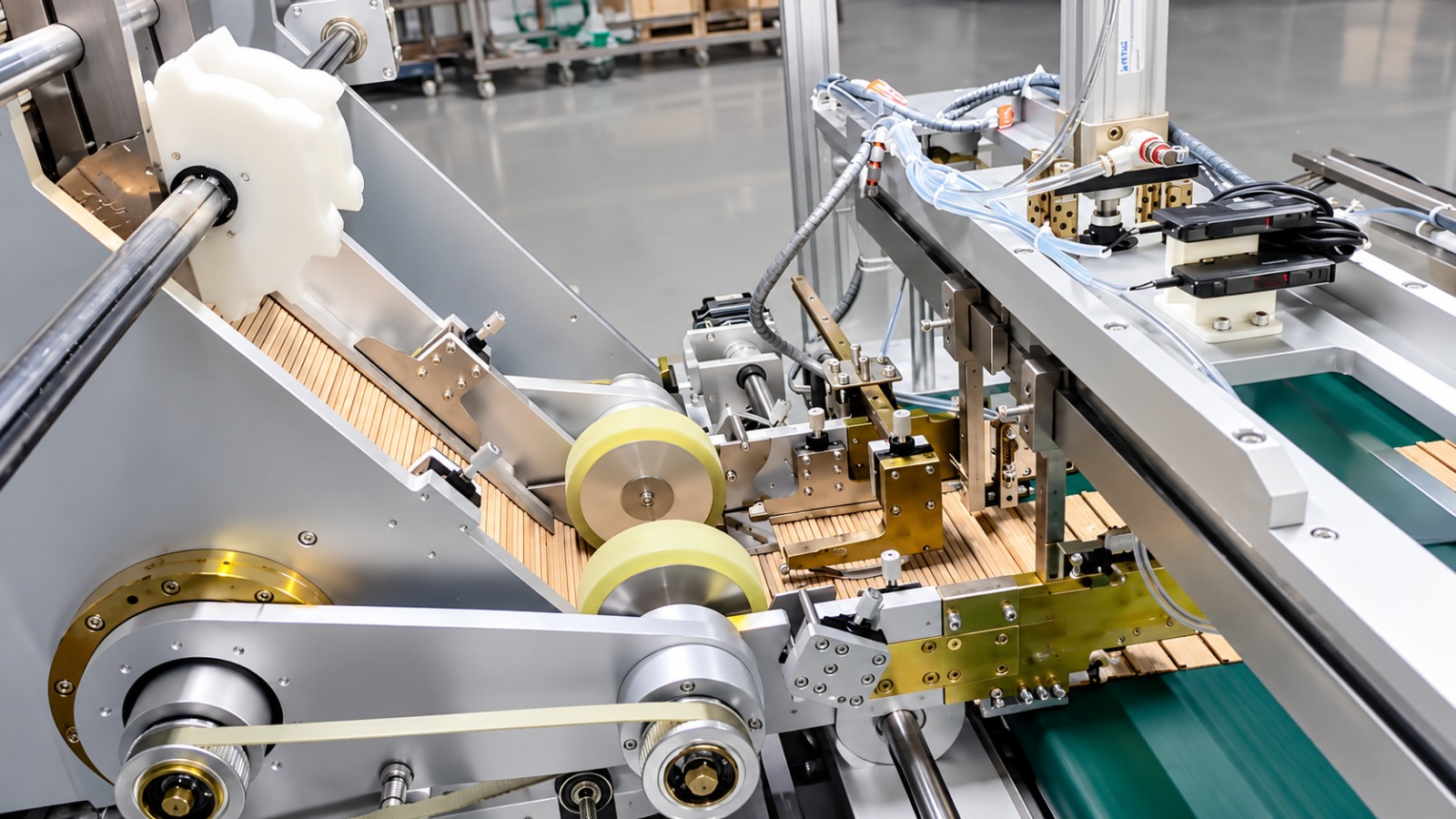
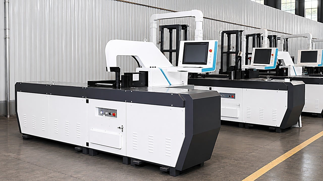
| Equipment | Servo CNC Busbar Bending Machine |
| Application | Flat and vertical bending of copper and aluminium busbars for switchgear, compact substations, transformers and bus duct production |
| Region | Kuala Lumpur, Malaysia — switchgear and bus duct manufacturing |
A switchgear manufacturer in Kuala Lumpur bent busbars on a manual machine with a square and a scribed line — angle by feel, length by tape, every size change paid for in trial bends and shims at assembly. After commissioning a servo CNC busbar bending machine with CAD/CAM programming, stopper positioning settled at ±0.15 mm and bending accuracy at ±0.3, a size change became a program edit instead of a die re-set, and busbars from the same batch now assemble interchangeably without re-fitting.
1. Customer Background: A Busbar Shop in Kuala Lumpur, Malaysia
This customer, based in Kuala Lumpur, Malaysia, supplies fabricated busbar sets to switchgear, compact substation and bus duct projects across Malaysia and Southeast Asia. Bending is the last forming operation before a busbar set goes into the enclosure, and once the angle or the position is off, the error has to be recovered with shims and on-site fitting.
The work used to run on a manual bending machine with a square and a scribed line: one angle per setup, length set by hand, so the quality of the finished set depended on the operator’s feel. As the order book shifted from standard enclosures to many ratings in small batches, the bending stage could no longer hold either repeatability or tempo against the assembly line.
After comparing several suppliers, the customer chose our NC.40ZB series servo CNC busbar bending machine.
2. Why Manual Busbar Bending Cannot Hold Repeatability in Small Batches
Busbar bending has to land on the correct angle and position the first time: scattered angles across one set accumulate into holes that will not line up inside the enclosure. The customer’s original method had six problems that would not go away:
- Angle set by feel. A manual bending machine controls angle through a stop block and experience, so angles scatter across a batch and holes will not line up at assembly.
- Length measured by hand. Bend positions were scribed from a tape measure; on bars over a metre long, one operator cannot hold a reliable measurement and two operators end up lifting and measuring together.
- Re-setting for every specification change. Each change of busbar size or bend form meant re-adjusting the stop and the dies, and setting time ran longer than machining time.
- Flat and vertical bends in two passes. Flat bending and vertical bending of the same bar ran as two operations in two clampings, and the clamping error stacked straight into the finished part.
- Bending disconnected from punching and shearing. Holes and cuts were made on a separate machine, leaving no common datum between hole positions and bend positions — the operator matched them by hand.
- Dependence on skilled hands. Angle and position lived with the most experienced operator; new staff took a long time to reach spec, and accuracy dropped whenever the operator changed.
Facing the same repeatability limits in your busbar shop? Get a busbar bending configuration and quotation →
3. Machine Configuration and Solution
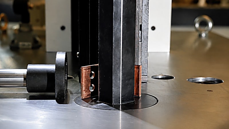
We configured the servo CNC busbar bending machine around the maximum cross-section, longest bar and common bend forms in the customer’s busbar schedule:
- Servo main drive with CNC control. The spindle is driven by a large-inertia servo motor (Rexroth) with a Beckhoff programmable controller and an industrial computer, so bending travel and repeated positioning are unaffected by temperature, and the machine stops automatically on standby to cut idle consumption.
- CAD/CAM programming. An independently developed CAD/CAM package is supplied with the machine, so bend sequences and angles are prepared on the computer and sent straight to the machine instead of being dialled in by trial bends.
- Closed bending structure. The bending station uses a closed structure, which distributes force more rationally and raises mechanical strength compared with open bending, giving more even forming in flat bending and embossing.
- Linear guides and balanced force layout. Linear guides with a balanced force arrangement reduce the effect of partial loading and friction on screw life and machining accuracy (the screw itself is TBI).
- Accuracy set to assembly requirements. Stoppers position to ±0.15 mm and bending accuracy is ±0.3, so angles repeat across a batch and the enclosure no longer needs shimming to line up.
- Models graded by bar length and cross-section. NC.40ZB-1200 gives a 1200 mm stopper length and 15 × 160 mm flat bending; NC.40ZB-2000 gives 2000 mm and 15 × 200 mm. Both handle 12 × 120 mm vertical bending at 400 kN nominal pressure. With bars up to 1.8 m long and 15 × 200 mm sections, the customer selected the 2000 model.
- Can be paired with a punching and shearing machine. Through the CNC programming software the bending machine works alongside a CNC busbar punching and shearing machine, with the two programs kept independent and maintenance straightforward.
4. Installation, Commissioning and Operator Training
After the machine arrived, TRANFOVIA engineers worked through three steps with the customer’s busbar shop:
- Schedule and selection review. The busbar list was checked for a maximum bar length of 1800 mm, a maximum cross-section of 15 × 200 mm and the common flat and vertical bend forms, the 2000 model was confirmed to cover them with margin, and the programming interface with the existing CNC punching and shearing machine was agreed.
- Site and dry running. The 4300 × 1450 × 1850 mm footprint and 3300 kg machine weight were used to confirm the foundation and the lifting route, the machine was connected to AC 380 V ±10% / 50 Hz, and a no-load run verified spindle travel, the foot switch, emergency stops and guards one by one.
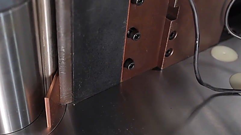
- Trial bending and acceptance. The customer supplied copper bars in the two common sizes, 15 × 160 mm and 15 × 200 mm, bend sequences and angles were entered in the CAD/CAM software and trial bent, stopper positions and bend angles were sampled to confirm that repeating a program gives the same result, and operators were trained on program preparation, die changes and daily checks using the English operation and maintenance manuals.
5. Acceptance Results: Manual Bending vs Servo CNC
The machine was verified item by item against the technical agreement. Key parameters (design and acceptance reference values; actual figures depend on the configuration ordered):
| Parameter | Manual bending machine (before) | Servo CNC busbar bending machine (after) |
|---|---|---|
| Bend angle | Stop block + operator feel, scatters across batch | ±0.3, repeatable program to program |
| Bend position | Tape-measure scribing, two operators on long bars | ±0.15 mm stopper positioning, one operator |
| Specification change | Re-set stop and dies, trial bends | Edit or call up stored program |
| Flat / vertical bends | Two operations, two clampings | One machine, both forms |
| Batch interchangeability | Fit and shim at assembly | Assembles interchangeably, no re-fitting |
| Skill dependence | Accuracy lives with one operator | Accuracy lives in the program |
Additional machine parameters confirmed at acceptance:
| Parameter | Value / Result |
|---|---|
| Nominal pressure | 400 kN |
| Stopper length (NC.40ZB-1200 / 2000) | 1200 mm / 2000 mm |
| Maximum flat bending size | 15 × 160 mm / 15 × 200 mm |
| Maximum vertical bending size | 12 × 120 mm |
| Spindle travel | 200 mm |
| Main motor power | 7.5 kW |
| Stopper positioning accuracy | ±0.15 mm |
| Bending accuracy | ±0.3 |
| Machine dimensions | 4300 × 1450 × 1850 mm |
| Machine weight | 3300 kg (2000 model) |
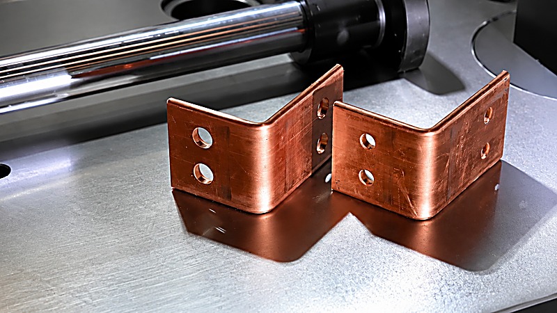
Through a full day of continuous bending at acceptance, every sampled bend angle and stopper position sat inside the accuracy window, and busbars from the same batch assembled interchangeably without re-fitting. The customer compared this with the manual bending machine it replaced: for the same 15 × 200 mm copper bar, the old route meant a stop block, trial bends and a re-setting for every size change, while the new machine calls up a stored bend sequence and angle, and a size change means editing the program instead of touching the dies.
6. What the Customer Says
“Bending used to depend entirely on the operator’s feel, and if the angle was a little off we paid for it with shims and fitting at assembly. Now the angle and the stopper position live in the program, a size change is just a program change, and busbars from the same batch assemble interchangeably without being lined up again.” — Customer busbar shop process supervisor (at acceptance)
7. Summary: Moving Angle and Position into the Program
The value of a servo CNC busbar bending machine is not that it can bend busbar, but that angle and position are taken out of the operator’s hands: a large-inertia servo drive with CNC and CAD/CAM programming lets bend sequences be prepared in advance and called up by enclosure type; a closed bending structure with a linear-guide force layout keeps forming even in both flat and vertical bending; ±0.15 mm stopper positioning and ±0.3 bending accuracy hand consistency to the machine, while 400 kN of nominal pressure and 15 × 200 mm flat bending cover the busbar sections that switchgear work normally calls for.
Next, the customer plans to build a standard program library holding the bend sequence and angles for each enclosure type, so that a given enclosure is simply called up, and to evaluate running the bending machine and the existing CNC busbar punching and shearing machine off one set of CNC programs so that punching, shearing and bending share a single busbar drawing.
To configure a busbar bending solution around your busbar schedule, longest bar and shift output, contact the TRANFOVIA technical team for selection advice and a quotation.
- WhatsApp: +86-15958243831
- Email: sales@tranfovia.com
- Website: https://tranfovia.com/