TL;DR:
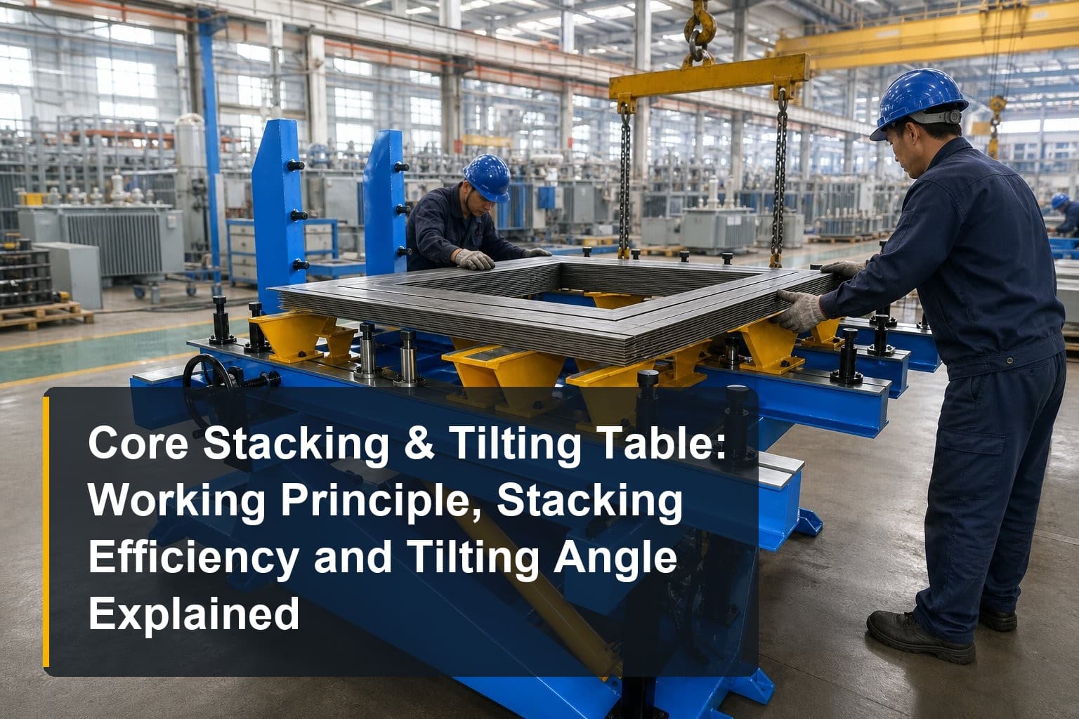
- A core stacking & tilting table holds a transformer core horizontally while laminations are stacked, then tilts the finished core 90° upright for coil assembly.
- Stacking efficiency — how quickly and accurately laminations become an ordered core — depends on platform modularity, datum design, and clamp access.
- Tilting angle control and clamping method decide whether the stacked core survives the turn without deformation: quality tables hold table deformation ≤3 mm and vertical deviation ≤2 mm after turning.
- Output quality is governed by lamination discipline, clamping sequence, and platform rigidity — all controllable with the right setup habits.
How does a core stacking & tilting table work, and which specifications actually define a good one? This article explains the working principle and key stages of the machine, shows how stacking efficiency influences equipment performance, covers the process essentials of tilting angle and clamping method, and closes with the factors that shape output quality along with practical optimization tips for transformer core assembly shops.
Working Principle and Key Stages of a Core Stacking & Tilting Table
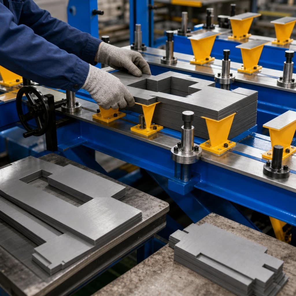
The working principle of a core stacking & tilting table is straightforward in concept and demanding in execution: provide a rigid, precisely flat horizontal platform on which the core is stacked lamination by lamination, clamp the finished stack securely, then rotate the entire platform 90° so the core stands upright for the next process. Three stages define the cycle.
Stage 1: Platform Setup and Datum Configuration
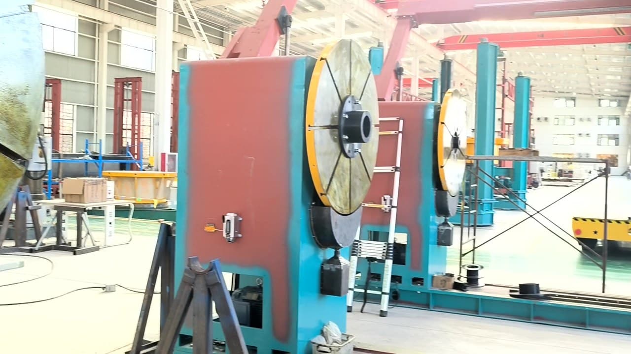
Before the first lamination is placed, the table is configured for the specific core. Modular platform sections are arranged to match the core window size — three platforms for a three-limb core, five for a five-limb design — and adjustable support posts and datum stops are set to the core drawing. This modularity is what allows one table to serve many core sizes: the working surface is effectively rebuilt for each product family, so the core’s geometry is referenced against hardened, positioned datums rather than improvised shims.
Stage 2: Horizontal Stacking of the Core
Stacking proceeds with the core lying flat, which is the whole ergonomic point of the machine. Lamination packets — ideally delivered pre-sorted from the cutting line — are laid step-lap layer by step-lap layer, with operators working at waist height instead of climbing scaffolding around a vertical core. Guide pins, edge stops, and the platform’s flatness keep every layer registered, while clamping beams hold completed sections. For medium and large power transformers, this horizontal method is what makes single-operator handling of wide laminations practical at all.
Stage 3: Clamping and the 90° Tilt
Once stacking is complete and the core is clamped as a unit, the platform tilts to vertical. On platform-type tables this turn is powered by the workshop crane acting on the tilting frame — no pit, no dedicated hydraulic power pack, and no additional energy consumption. Anti-overturn outriggers engage to stabilize the table past 90°, and the synchronized frame design keeps the core from shifting during rotation. The upright core is then ready for lifting into the coil assembly process.
How Stacking Efficiency Influences Equipment Performance
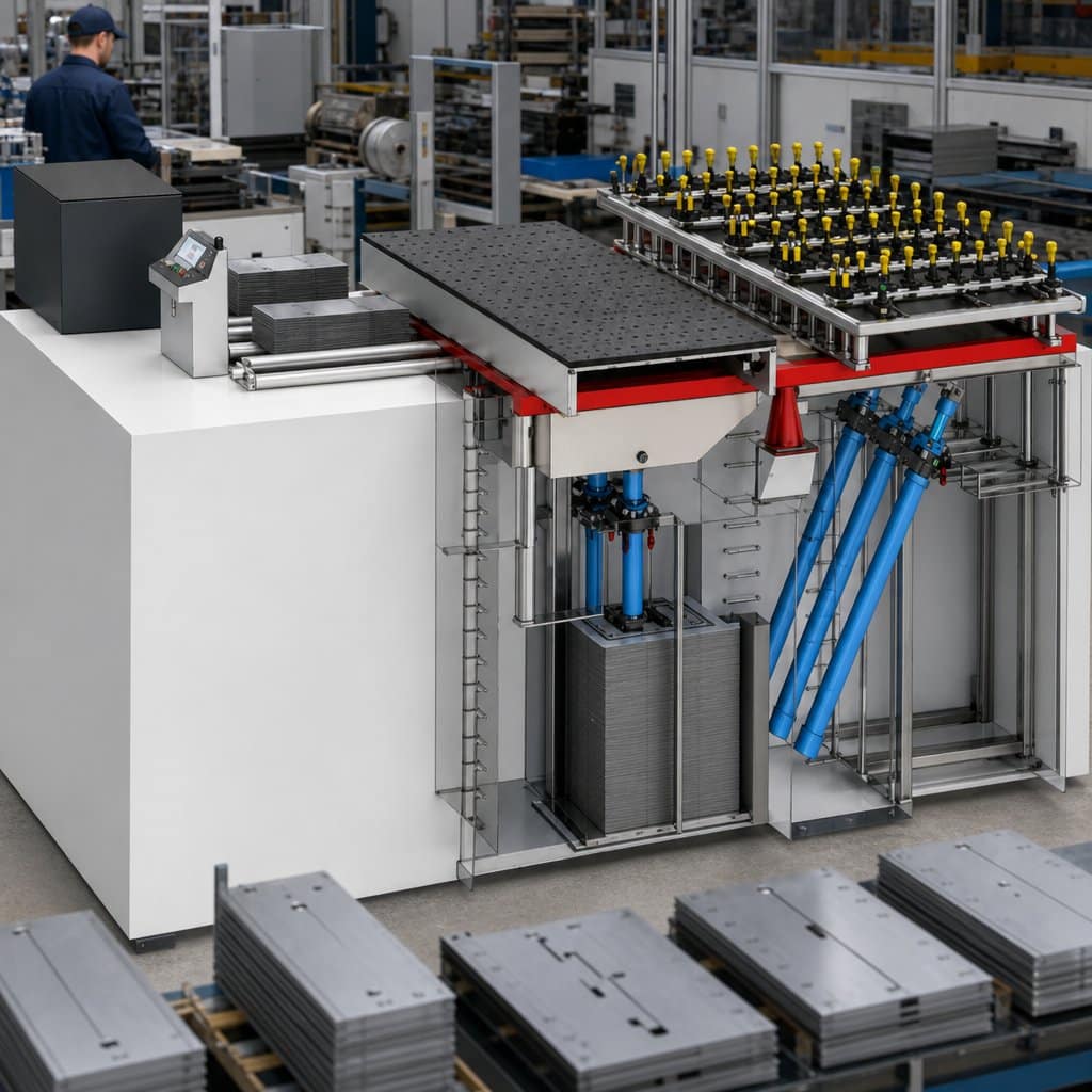
Stacking efficiency — laminations placed correctly per shift, with minimal rework — is where a core stacking & tilting table earns or destroys its value. The machine contributes through three mechanisms: platform design, datum repeatability, and integration with the upstream cutting line.
Platform Modularity and Setup Time
A modular platform that reconfigures to each core window size by repositioning standard sections converts setup from fabrication to adjustment. Tables with pinned, numbered platform positions let operators reproduce a proven setup in minutes; tables that require measuring and shimming every time burn hours per changeover and invite datum errors. When comparing specifications, ask how platform positions are indexed and documented, because repeatability of the setup is what turns modularity from a brochure word into shift-level efficiency.
Datum Design and Registration Accuracy
Every lamination must register against the same datums or the step-lap pattern wanders and the core window distorts. Well-designed tables provide ground datum edges and positive stops at each limb position, so registration does not depend on operator judgment. This is where stacking efficiency and core quality meet: fast placement is only valuable when every layer lands in tolerance. The flatness and machining quality of the platform — precision-machined key surfaces on stress-relieved, FEA-verified weldments — is the foundation that datum accuracy stands on.
Feeding the Table: Upstream Integration
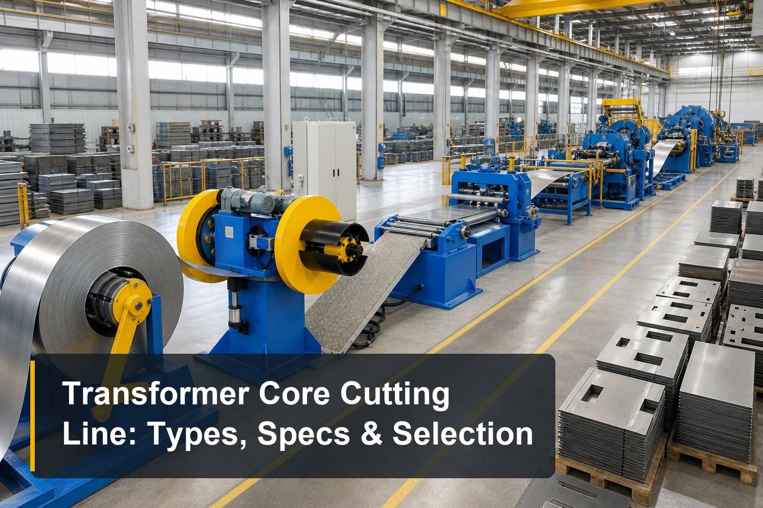
Stacking efficiency is capped by how laminations arrive. A stacker waiting on mixed, unsorted sheets loses more time than any platform feature can recover. Pairing the table with a servo sorting core cutting line that delivers sequenced, pre-stacked lamination packets removes sorting from the stacking station entirely — the operator places complete step-lap groups in order. In high-mix core shops this integration routinely matters more than any single machine’s speed.
Process Essentials: Tilting Angle and Clamping Method
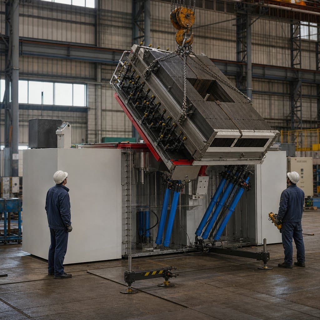
The tilt is the moment of truth: tonnes of stacked laminations rotate from horizontal to vertical, and only the clamping method and the frame’s rigidity keep the core’s geometry intact. Understanding tilting angle control and clamping essentials is central to specifying and operating the table correctly.
Tilting Angle Control and Synchronization
The table must reach a true 90° — and hold it — without rack or drift. Quality tables specify vertical deviation after turning at ≤2 mm, with table deformation during the tilt held to ≤3 mm even under full core weight. Crane-powered turning achieves this through synchronized linkage geometry: the crane supplies the force, but the frame’s design determines whether that force rotates the core smoothly or twists it. Anti-overturn outriggers that deploy past the vertical point are the essential safety feature, preventing instability exactly where the load is most precarious.
Clamping Method and Sequence
Clamps must immobilize the stack without crushing it. The method that works is distributed clamping: beams and screws at multiple points per limb, tightened in a balanced sequence from the center outward, pressing laminations together evenly rather than pinching one edge. Clamping force matters less than clamping uniformity — local over-tightening dents the outer laminations and distorts the step-lap joints the cutting line worked to make precise. Adjustable clamp posts that reposition for each core size keep pressure points where the drawing intends them.
Platform Rigidity as a Process Variable
Rigidity belongs in this discussion because tilting angle accuracy is only as good as the structure delivering it. Heavy-duty welded frames that have undergone aging treatment for stress relief hold their machined flatness over years; frames without stress relief warp slowly and show up as creeping vertical deviation. Finite element analysis during design — and verified deformation figures in the specification — is what separates a table engineered for a 50-tonne core from one merely rated for it.
Factors That Influence Output Quality and Optimization Tips
Core quality at the stacking table depends on lamination condition, operator discipline, and platform maintenance more than on any headline specification. These factors are all controllable, and the tips below address each one.
Lamination Condition and Handling Discipline
A stacking table cannot fix damaged laminations. Burrs, bent edges, or oil contamination on incoming sheets translate directly into local gaps and elevated core loss. Establish an incoming check at the table: sample-measure burr, reject deformed packets, and keep handling gloves and surfaces clean. Store lamination packets flat and covered near the table so the last process before assembly never degrades what the cutting line produced.
Stacking Sequence and In-Process Checks
Output quality is built layer by layer, so check early rather than at the end. Verify the step-lap registration and window dimensions after the first complete layer group, not after the last — a systematic offset caught at layer five costs minutes, caught at completion it costs the core. Keep the core drawing at the station, mark completed groups, and assign one operator ownership of datum checks per shift. These habits cost nothing and prevent nearly all stacking rework.
Platform Maintenance and Periodic Verification
Platform flatness drifts with use, and the tilt mechanism wears. Measure platform flatness and post-turn vertical deviation on a schedule — quarterly for busy shops — and recalibrate datums against a reference straightedge. Keep the crane interface points and outrigger pivots lubricated and inspected, since the tilt depends on them. When the core leaves the table for the coil assembly platform, its geometry should be documented so any downstream issue can be traced to its true stage.
Frequently Asked Questions
What is the working principle of a core stacking & tilting table?
The table provides a rigid horizontal platform on which the transformer core is stacked lamination by lamination at ergonomic working height. Once stacking is complete and the core is clamped, the entire platform tilts 90° — on platform-type models powered by the workshop crane, with no pit or power pack required — bringing the core upright for coil assembly. Modular platform sections adapt the table to different core window sizes.
What specifications matter most when choosing a table?
Focus on the numbers that survive contact with a real core: table deformation during turning ≤3 mm, vertical deviation after turning ≤2 mm, platform flatness, and the tonnage class — model series typically run from FT02 up to FT450 to match core weights. Also verify the anti-overturn protection design and whether the frame is FEA-designed and stress-relieved, since rigidity determines whether those figures hold for years.
Does the table need a pit or special foundation?
Platform-type stacking and tilting tables require neither a pit nor a special foundation — they install directly on the workshop floor, saving construction cost and layout flexibility. The tilt is driven by the existing overhead crane. Pit-mounted automatic designs with hydraulic drives exist for very large cores, but they demand civil works and higher investment.
How many platforms do I need for my core design?
Match the platform count to the limb count: three platforms for three-limb cores, five for five-limb cores. The modular sections are configured to the core window size, so one table covers a family of designs. Provide your core drawings to the supplier so the platform layout, support posts, and clamp positions are configured for your range before delivery.
Summary
A core stacking & tilting table works by stacking the transformer core horizontally on a rigid modular platform, clamping it as a unit, and tilting it 90° to vertical — crane-powered, pit-free, and energy-free on platform-type designs. Its real performance is defined by stacking efficiency, tilting accuracy (≤2 mm vertical deviation, ≤3 mm deformation), and clamping uniformity, and output quality stays high when lamination condition, in-process checks, and platform maintenance are treated as disciplines rather than afterthoughts.
TRANFOVIA supplies core stacking and turning tables from FT02 to FT450 for medium and large power transformer cores, with modular platforms configured to your core drawings. For sizing and layout advice, contact TRANFOVIA today.
📞 +86-15958243831 📧 sales@tranfovia.com 💬 WhatsApp: https://wa.me/8615958243831 🌐 tranfovia.com
References
- IEC 60076-1:2011. Power transformers — Part 1: General. International Electrotechnical Commission. https://webstore.iec.ch
- IEEE Std C57.12.00-2015. IEEE Standard for General Requirements for Liquid-Immersed Distribution, Power, and Regulating Transformers. IEEE. https://standards.ieee.org
- ASTM A876/A876M. Standard Specification for Flat-Rolled, Grain-Oriented, Silicon-Iron, Electrical Steel. ASTM International. https://www.astm.org
- IEC 60404-8-7. Magnetic materials — Specifications for individual materials — Cold-rolled grain-oriented electrical steel. International Electrotechnical Commission. https://webstore.iec.ch
- Kulkarni, S. V., & Khaparde, S. A. (2004). Transformer Engineering: Design and Practice. Marcel Dekker.
- Georgilakis, P. S. (2009). Spotlight on Modern Transformer Design. Springer.