Secondary Silicon Steel Cutting Line: How to Reuse CRGO Remnants for Transformer Cores
Every transformer core shop generates them: offcuts from the slitting line, leftover coil tails, sheets rejected for length but not for quality. In many factories this material piles up in a corner until it is sold as scrap — at a fraction of the price of prime CRGO. A secondary silicon steel cutting line exists to change that equation. It recuts usable remnants into production-ready laminations, turning a waste stream back into core material.
This guide explains what a secondary silicon steel cutting line does, how it works, what its specifications mean in practice, and how to decide whether your factory needs one.
What Is a Secondary Silicon Steel Cutting Line?
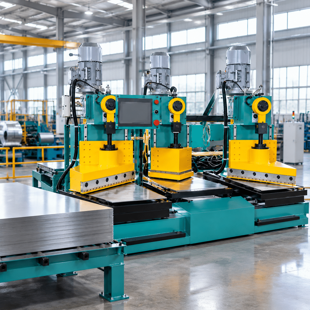
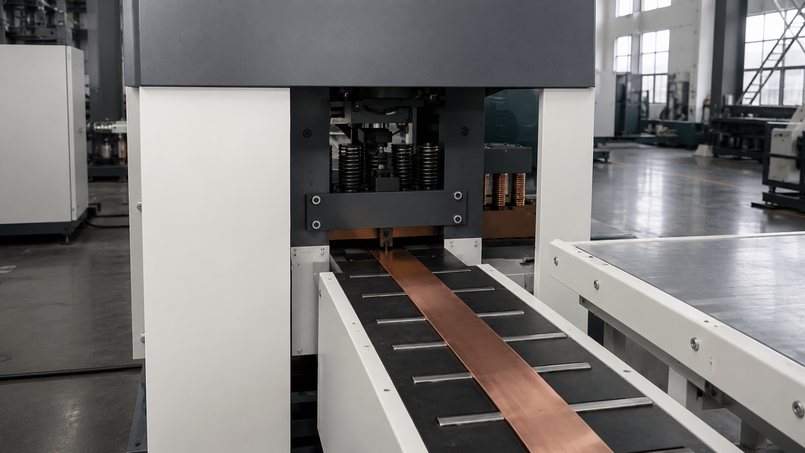
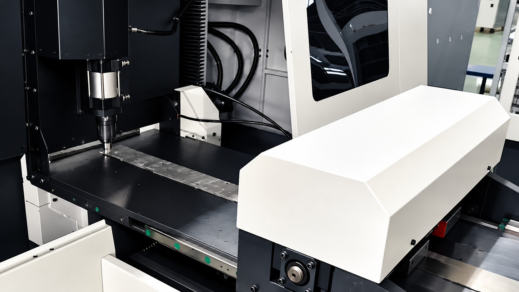
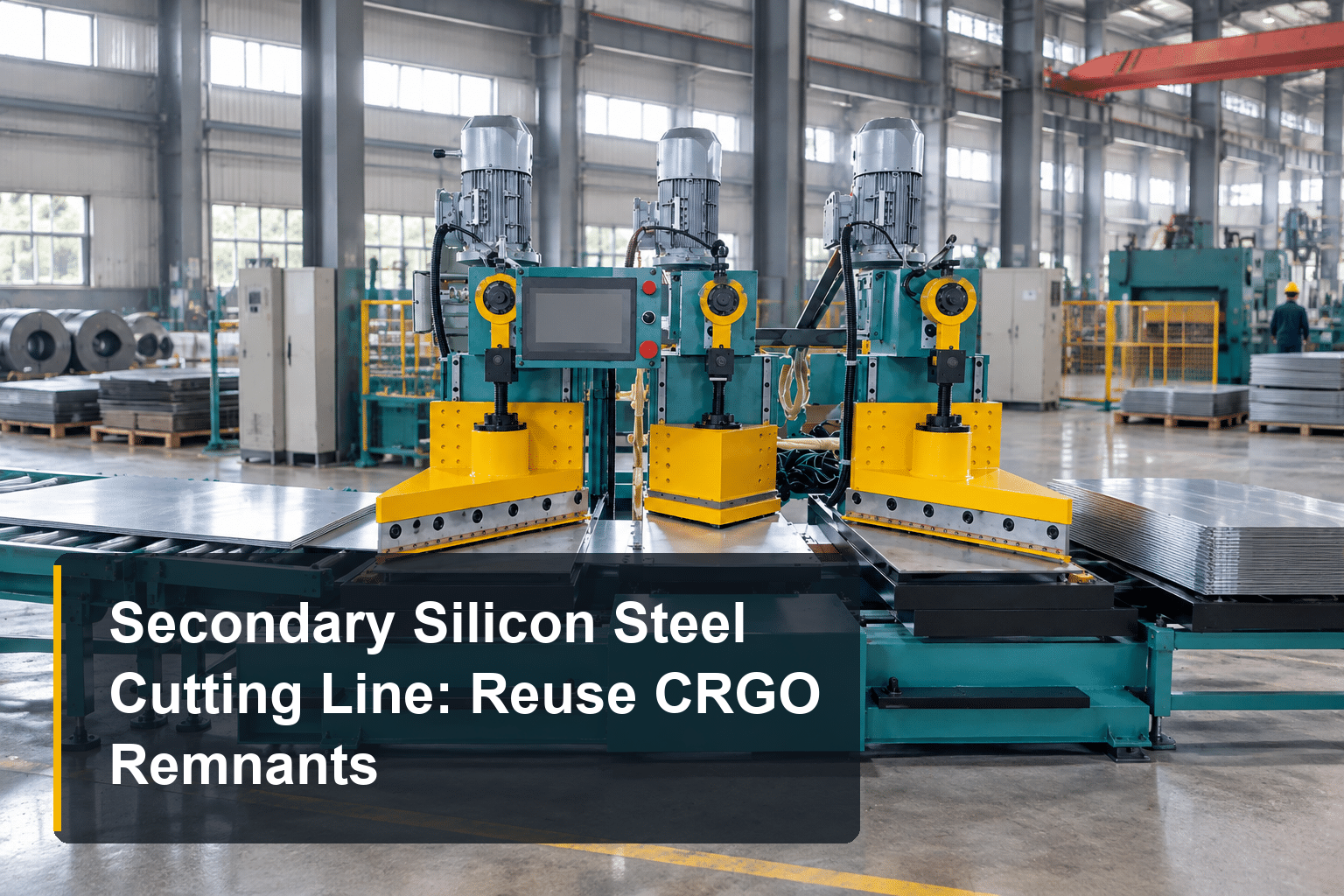
A secondary silicon steel cutting line is a compact cut-to-length machine designed for one job: processing silicon steel sheets and strips that have already been through primary preparation, but need additional cutting before they can be used in a transformer core.
That “secondary processing” covers several everyday situations:
- Cutting remaining or reused CRGO sheets to new lengths
- Recutting wider strips into narrower laminations
- Preparing additional lamination sizes that a production run ran short of
- Handling small recut jobs without occupying the main transformer core cutting line
The key word is flexible. A full core cutting line is built for continuous coil processing at high speed. Interrupting it for a 200-sheet recut job costs setup time, blade changes, and production slots. A secondary line absorbs this work at a fraction of the size and power — the four standard models draw just 6.6–7 kW in total.
Why CRGO Remnants Are Worth Reusing
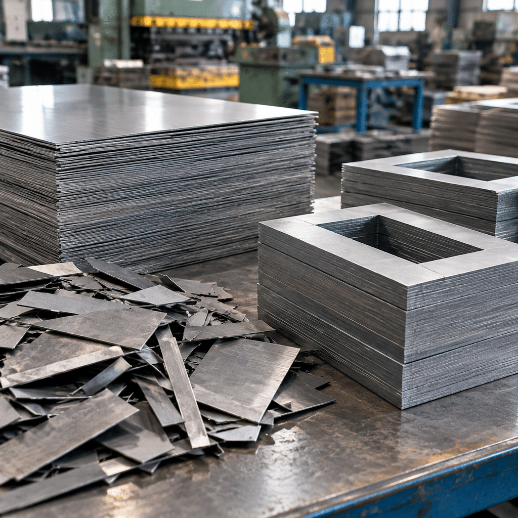
CRGO electrical steel is one of the most expensive materials in a transformer factory — in most markets it sells at several times the price of ordinary steel scrap. Yet in most core shops, a measurable share of every coil ends up as offcuts, coil tails, and sheets that fail length or shape checks while remaining perfectly sound in magnetic quality.
Selling this material as scrap recovers only its weight in low-grade steel value. Recutting it into usable laminations preserves its value as transformer-grade steel. For repair and refurbishment workshops the logic is even stronger: reused core material is often the only economical way to rebuild older transformers whose original lamination sizes are no longer standard production items.
The catch is that remnant material is unforgiving to process. Sheets arrive in mixed sizes, often with sheared edges from previous operations. To make them production-ready again, the cutting process must deliver consistent length, stable feeding, and — critically — low burr, because burr on a lamination edge creates interlaminar shorts that raise no-load losses in the finished core.
How the Line Works: Feeding, Shearing and Length Control
The working principle is straightforward but must be executed precisely:
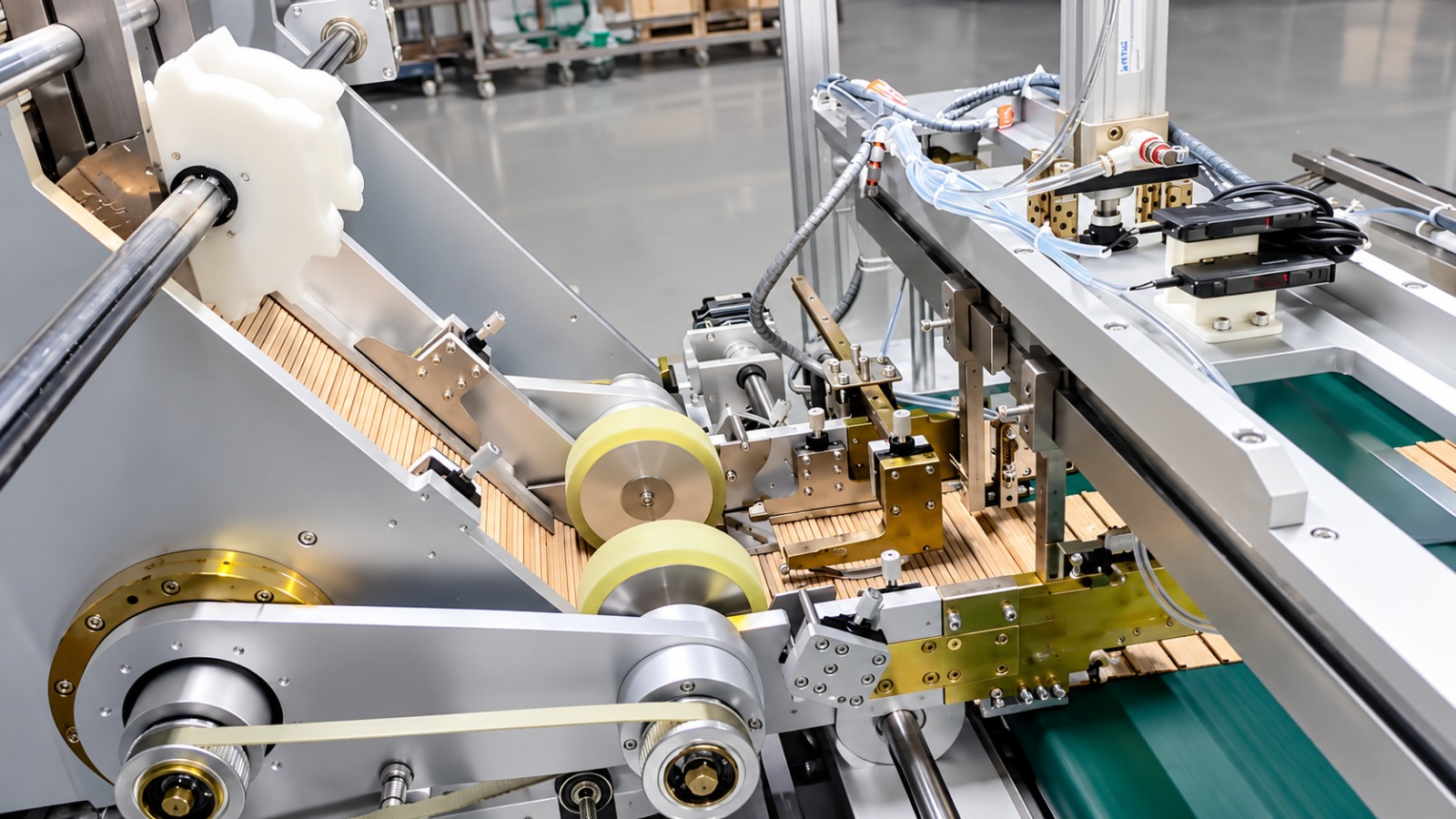
1. Feeding. The sheet or strip is advanced by a controlled feeding system. Because secondary material is often short, narrow, or slightly edge-damaged, feeding stability matters more than raw speed — any deviation during feeding shows up directly as length error or angled cuts.
2. Shearing. The material is cut by a shear blade, not punched. This distinction matters: shearing cuts a sheet to length or width in a single straight action, while punching makes holes or slots — a different process with different tooling. For lamination recutting, clean shearing with a sharp, correctly gapped blade is what keeps the cut edge within the ≤0.02 mm burr specification. If you want a deeper look at how cut-to-length shearing works on prime material, our silicon steel cutting machine guide covers the fundamentals.
3. Length control. Cut length is set electronically within the machine’s range — for example 330–1500 mm on the 200 mm-wide models. Consistent length across a batch is what allows the recut sheets to go straight into core stacking without sorting or rework.
Key Specifications: Four Standard Models
The secondary material silicon steel cutting line comes in four configurations. All share the same thickness range and burr specification; they differ in width and length capacity:
| Item | XE-X-200M | XE-X-300M | XE-ZZ-200M | XE-ZZ-300M |
|---|---|---|---|---|
| Cutting Thickness | 0.23–0.5 mm | 0.23–0.5 mm | 0.23–0.5 mm | 0.23–0.5 mm |
| Cutting Width | 30–200 mm | 30–300 mm | 30–200 mm | 30–200 mm |
| Cutting Length | 330–1500 mm | 440–2000 mm | 420–1500 mm | 460–1500 mm |
| Cutting Burr | ≤0.02 mm | ≤0.02 mm | ≤0.02 mm | ≤0.02 mm |
| Total Motor Power | 7 kW | 7 kW | 6.6 kW | 6.6 kW |
Three numbers deserve attention when you read this table:
- 0.23–0.5 mm thickness covers the standard CRGO grades used in distribution and power transformer cores — the same range as primary cutting equipment.
- 30 mm minimum width means the line can handle narrow remnant strips that would be impractical to recut manually.
- ≤0.02 mm burr is the figure that decides whether recut material is actually core-grade. Any cutting equipment you consider for material reuse should be held to this level.
Which Materials Are Suitable — and Which Are Not
A common misunderstanding is that a “secondary material” line is a scrap processor. It is not. The machine cuts metal accurately; it cannot repair metallurgy. The material you feed it must still meet your quality requirements for the intended core application:
- Suitable: offcuts and coil tails from known CRGO grades, sheets rejected for length or width (not for coating or magnetic defects), and cores recovered from repair projects where the steel grade is documented or verified.
- Not suitable: material with damaged insulation coating, rust, unknown provenance, or magnetic degradation. No amount of precise cutting makes such material acceptable for a transformer core.
In practice, factories that get the most from a secondary cutting line are those that sort remnants at the source — keeping usable offcuts separate from true scrap, labeled by grade and thickness.
How to Choose the Right Model for Your Factory
Model selection follows the dimensions of the material you actually need to recut. Work through this order: thickness → width → length → burr → workflow fit.
- Mostly narrow strips under 200 mm? The XE-X-200M or XE-ZZ-200M covers 30–200 mm width with lengths to 1500 mm — sufficient for most distribution transformer laminations.
- Need the widest and longest range? The XE-X-300M handles up to 300 mm width and 2000 mm length, covering larger core designs and giving headroom for future product mix changes.
- Running a repair workshop? Prioritize length flexibility and feeding stability over width, since repair laminations are often non-standard in length.
One final question worth asking yourself: how often does your main cutting line stop for small recut jobs? If the answer is “weekly” or more, the recovered production time alone usually justifies a dedicated secondary line — before you even count the material savings.
If you are evaluating whether a secondary line makes sense for your shop, the natural next step is our guide to choosing a silicon steel cut-to-length machine — and if you already have remnant sizes and core drawings on hand, we are glad to recommend a model that fits.