| Customer | A distribution transformer manufacturer in Nairobi, Kenya |
| Application | CNC machining of transformer insulation components |
| Workpieces | Pressboard end rings, platens and conductor clamps |
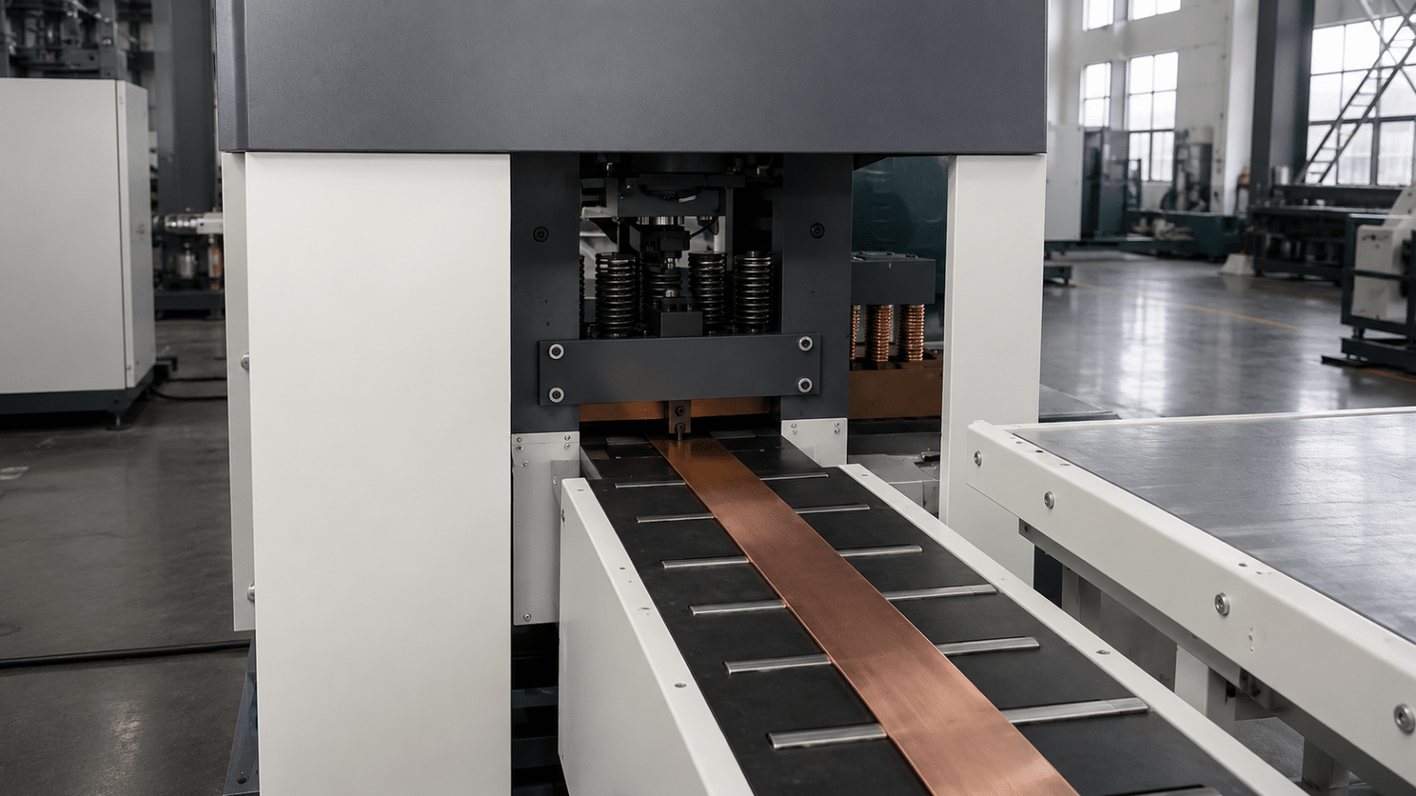
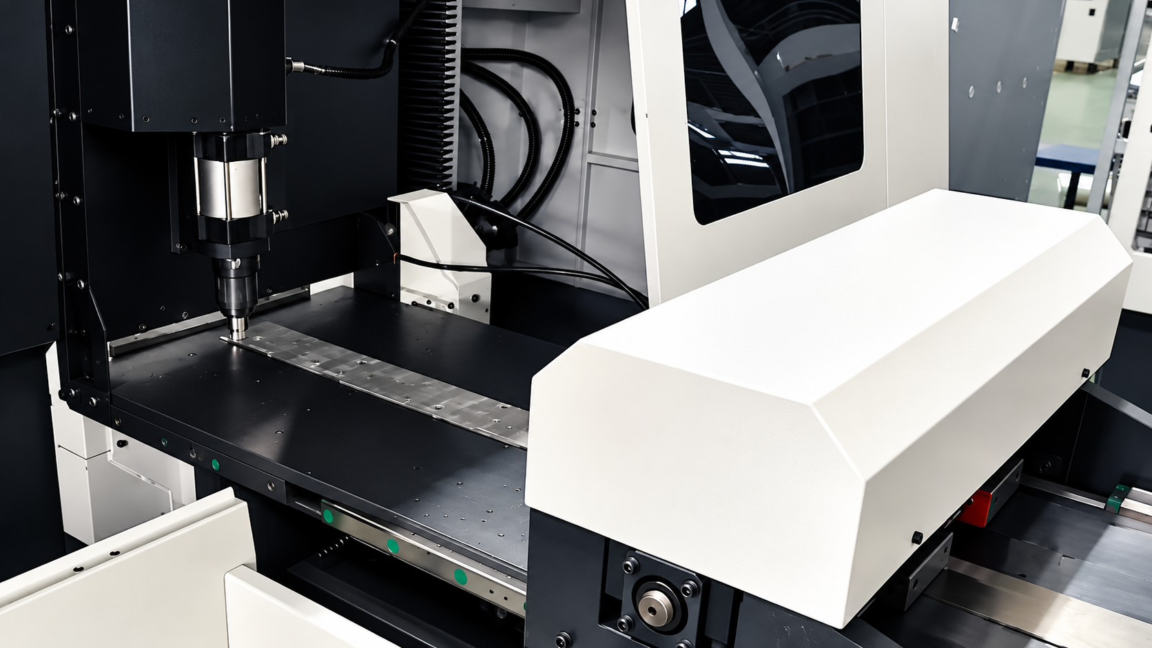
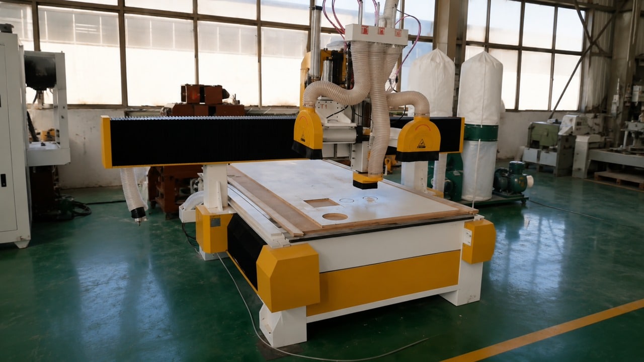
| Equipment | CNC Transformer Insulation Parts Processing Center |
1. Customer Background: Managing Insulation Parts In-House
The customer manufactures distribution transformers for projects in Kenya and neighbouring East African markets.
Its large structural insulation components, including end rings, platens and conductor clamps, were previously purchased from external suppliers. Delivery schedules depended on supplier availability, while parts that did not meet the customer’s requirements could require rework in its own workshop.
To reduce the risk of production delays, the manufacturer maintained inventory across multiple part numbers. This tied up working capital and made it harder to respond flexibly when production requirements changed.
The existing workshop relied on a general-purpose milling machine and a hand drill press. End-ring profiles were laid out manually, and grooves were cut using hand feed. Complex or non-standard parts often required subcontracting.
The manufacturer therefore evaluated a dedicated CNC machining solution that could handle large insulation components and consolidate multiple operations into a single setup.
2. The Main Challenges in Transformer End-Ring Machining
- Manual profile and groove machining
End-ring inner and outer diameters were set out from scribed lines, while ring grooves were machined using manual feed. Dimensional consistency depended heavily on the setup and operator technique.
- Repeated setups across separate machines
Profiling, groove machining, drilling and local surface machining were divided among several machines. Each transfer introduced another clamping and alignment step.
- Limited flexibility for non-standard components
Platens with cut-outs and asymmetric conductor clamps were difficult to produce with the existing workshop equipment, so these parts had to be subcontracted.
- Insulation dust and contamination control
Machining pressboard generates fine dust. The customer needed a machining arrangement that considered dust extraction and the prevention of metal contamination in electrical insulation components.
- Supplier lead times and inventory pressure
Purchased parts exposed the production schedule to external supplier backlogs. Maintaining stock across multiple part numbers helped reduce waiting time but tied up cash and storage space.
These challenges led the manufacturer to seek a solution that could improve machining flexibility while bringing more control over part production and scheduling into its own workshop.
3. The Solution: CNC Machining for Large Transformer Insulation Parts
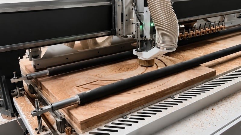
TRANFOVIA configured the machining solution around the customer’s largest end-ring diameter, thickest platen and commonly required groove profiles.
Large working strokes for end rings and platens
Two configurations are available:
- 1500 × 3000 mm: Maximum processing thickness of 100 mm, with a 6 kW main spindle.
- 3300 × 3300 mm: Maximum processing thickness of 120 mm, with an 11 kW main spindle.
The customer selected the 3300 × 3300 mm configuration to accommodate its largest end ring and thicker insulation components.
Multiple machining operations in one clamping
The CNC platform combines:
- Inner and outer contour milling
- Circular and straight groove machining
- Programmed drilling
- Local surface machining
This arrangement reduces the need to transfer the same workpiece between multiple machines. The machining sequence can be programmed from the component drawing, subject to the machine configuration, tooling and workpiece requirements.
Programmable profiles for customized components
Programmed contours allow the workshop to machine specified geometries without relying exclusively on manual layout or a dedicated template for every shape.
This is particularly relevant when end rings, platens and conductor clamps have different dimensions or non-standard profiles.
Flexible workpiece positioning
The machine uses an aluminium-alloy T-slot worktable for positioning and clamping workpieces. The setup can be arranged according to the shape and machining requirements of the component.
Dust extraction and contamination considerations
The equipment design incorporates dust-removal provisions and measures intended to reduce the risk of metal contamination during insulation machining. The extraction arrangement must be configured appropriately for the customer’s workshop and dust-collection system.
Machining accuracy and configuration
The specified positioning accuracy is:
- XY positioning accuracy: 0.2 mm
- Z positioning accuracy: 0.05 mm
These are machine positioning specifications, not a guarantee that every finished component will achieve the same dimensional tolerance. Actual part accuracy also depends on tooling, material, workholding, program settings and the acceptance method.
4. Implementation and Commissioning
Implementation covered drawing review, site preparation, machine checks, trial machining and operator training.
Step 1: Review drawings and confirm the configuration
The engineering team reviewed the customer’s end-ring and platen drawings, including maximum dimensions, thickness and groove profiles. The 3300 × 3300 mm working stroke and 120 mm maximum processing thickness were confirmed against the stated workpiece requirements.
The dust-extraction connection was also reviewed in relation to the workshop’s extraction ducting.
Step 2: Check the installation and machine operation
The foundation and lifting route were checked before commissioning. A dry run verified the three-axis travel, spindle start and stop functions, emergency stops, guarding and extraction interlocks.
Step 3: Conduct trial machining and acceptance checks
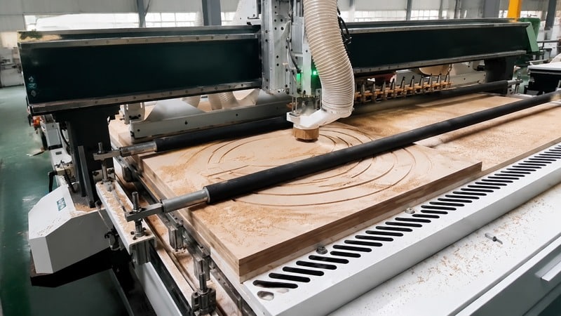
The customer supplied two commonly used end rings and one platen for trial machining.
Programs were prepared from the component drawings. The team sampled the inner and outer diameters, ring-groove positions, groove depths and hole pitch to check the machined parts against the agreed acceptance requirements.
The trial also allowed operators to become familiar with program preparation, tool changes and routine machine checks. English operation and maintenance manuals were provided.
5. Trial Machining and Acceptance Results
Three part numbers were machined in succession during the trial. The sampled dimensions were reported within the specified accuracy window, and end rings from the same batch assembled without additional fitting.
The customer’s previous route for the same end ring involved four operations and four re-clampings on a general-purpose milling machine. With the CNC processing center, the corresponding programmed machining route used one clamping and one program.
The key technical specifications of the two available configurations are shown below.
| Parameter | 1500 × 3000 Configuration | 3300 × 3300 Configuration |
|---|---|---|
| Effective working stroke | 1500 × 3000 mm | 3300 × 3300 mm |
| Maximum processing thickness | 100 mm | 120 mm |
| XY fast idle speed | 12 m/min | 40 m/min |
| Z fast idle speed | 3 m/min | 8 m/min |
| XY positioning accuracy | 0.2 mm | 0.2 mm |
| Z positioning accuracy | 0.05 mm | 0.05 mm |
| Main spindle speed | 0–24,000 r/min | 0–18,000 r/min |
| Main spindle power | 6 kW | 11 kW |
| Worktable | Aluminium-alloy T-slot | Aluminium-alloy T-slot |
These figures describe the specified machine configurations. They should not be interpreted as a measured production-cycle-time reduction or as a guarantee of finished-part tolerances for every application.
6. Customer Feedback
The customer’s insulation shop supervisor described the operational change at acceptance:
“Our end rings used to be bought in, so the lead time belonged to someone else’s schedule and anything out of tolerance we had to rework ourselves. Now the drawing and the finished part are both in our own shop, the profiles, grooves and holes come off one clamping, and we do not have to re-fit anything at assembly. The dust is captured as well, so the shop is cleaner than it was.”
The feedback highlights three practical considerations for insulation manufacturers: control over part scheduling, fewer machining setups and attention to dust collection.
7. What This Means for Transformer Insulation Workshops
For transformer manufacturers that process large end rings, platens and conductor clamps, bringing machining in-house can provide greater control over production scheduling and customized part requirements.
A CNC insulation parts processing center is worth evaluating when:
- Large insulation components exceed the practical working range of existing workshop machines.
- Profiles, grooves and holes need to be machined from engineering drawings.
- Repeated clamping and alignment steps complicate the existing process.
- Non-standard components create recurring subcontracting or lead-time issues.
- Dust extraction and prevention of metal contamination need to be considered as part of the machining setup.
The appropriate configuration depends on the maximum component dimensions, processing thickness, required operations, production volume and workshop conditions. Machine positioning accuracy should also be evaluated separately from the finished-part tolerance required by the drawing.
For a broader overview of the machines used to manufacture pressboard and other transformer insulation components, see our Transformer Insulation Parts Processing Guide.
8. Discuss Your Transformer Insulation Machining Requirements
If your workshop is considering bringing end-ring, platen or conductor-clamp machining in-house, the first step is to review the actual component drawings and production requirements.
The TRANFOVIA team can help assess the working stroke, processing thickness and machining configuration required for your parts.
Contact TRANFOVIA for a configuration review and quotation.
- WhatsApp: +86-15958243831
- Email: sales@tranfovia.com
- Website: https://tranfovia.com/