| Equipment | CNC Busbar Punching and Shearing Machine |
| Customer | A distribution transformer and compact substation manufacturer in Doha, Qatar |
| Application | Punching, shearing, chamfering and embossing of copper and aluminum busbars for transformer LV sides and compact substation internal connections |
Customer information has been anonymized; only regional and industry attributes are retained. Performance figures represent design and acceptance reference values and may vary depending on configuration and actual operating conditions.
1. Customer Background
The customer operates out of an industrial zone in Doha, building 11/0.4 kV distribution transformers and compact substations for substation, data centre and industrial park projects across the Gulf region. The busbar shop handles every LV-side busbar and every internal panel busbar in the product range — copper from 3×20 mm up to 15×200 mm, aluminum from 3×30 mm up to 12×120 mm.
For five or six years that shop ran on one 400 kN punching and shearing machine plus manual marking-out: hole diameter changed by swapping dies, hole position came from scribed lines and a mechanical stop, and every sheared lap face was finished by hand with an angle grinder. Order patterns used to be few projects in large batches; from 2024 onward they became many projects in small batches, with more than twenty drawing numbers cycling through the same quarter. Capacity and accuracy hit their ceiling at the same time.
2. Industry Pain Points
Insufficient capacity pushed main busbars to subcontractors. The old machine was rated 400 kN, 12×160 mm maximum working size and ⌀25 mm punching limit. A 15×200 mm busbar with a ⌀35 mm hole could not be done in one pass, so it was subcontracted out — putting delivery dates outside the customer’s control.
Die changes consumed a large share of machine hours. Each hole diameter needs its own die set, and one drawing can call for a dozen or more hole sizes. Every change meant stopping the machine to strip, fit and re-align a die — actual punching time was under half of the working day.
Re-clamping long bars accumulated hole-pitch error. A 6 m copper bar had to be machined in segments, and every repositioning introduced another positional error. Once hole pitch drifted, busbars would not line up during assembly, and holes had to be opened up on site or the part scrapped.
Sheared faces carried waste strips, burrs and collapsed corners. Every cut produced a waste strip and a sheared edge with burrs and a collapsed corner, so lap faces had to be ground by hand before they would seat — extra labour and inconsistent contact-surface quality.
Accuracy depended on operator feel. Hole position came from scribed lines plus a mechanical stop, so error drifted from batch to batch and a stable 0.10/500 mm was out of reach.
3. Solution
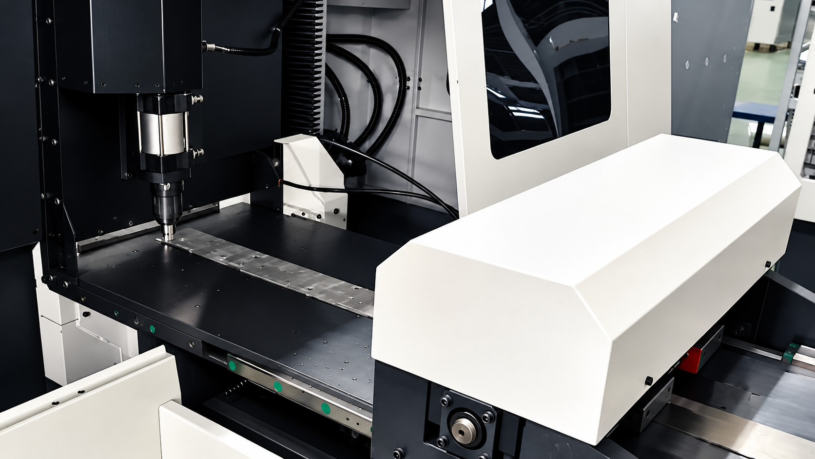
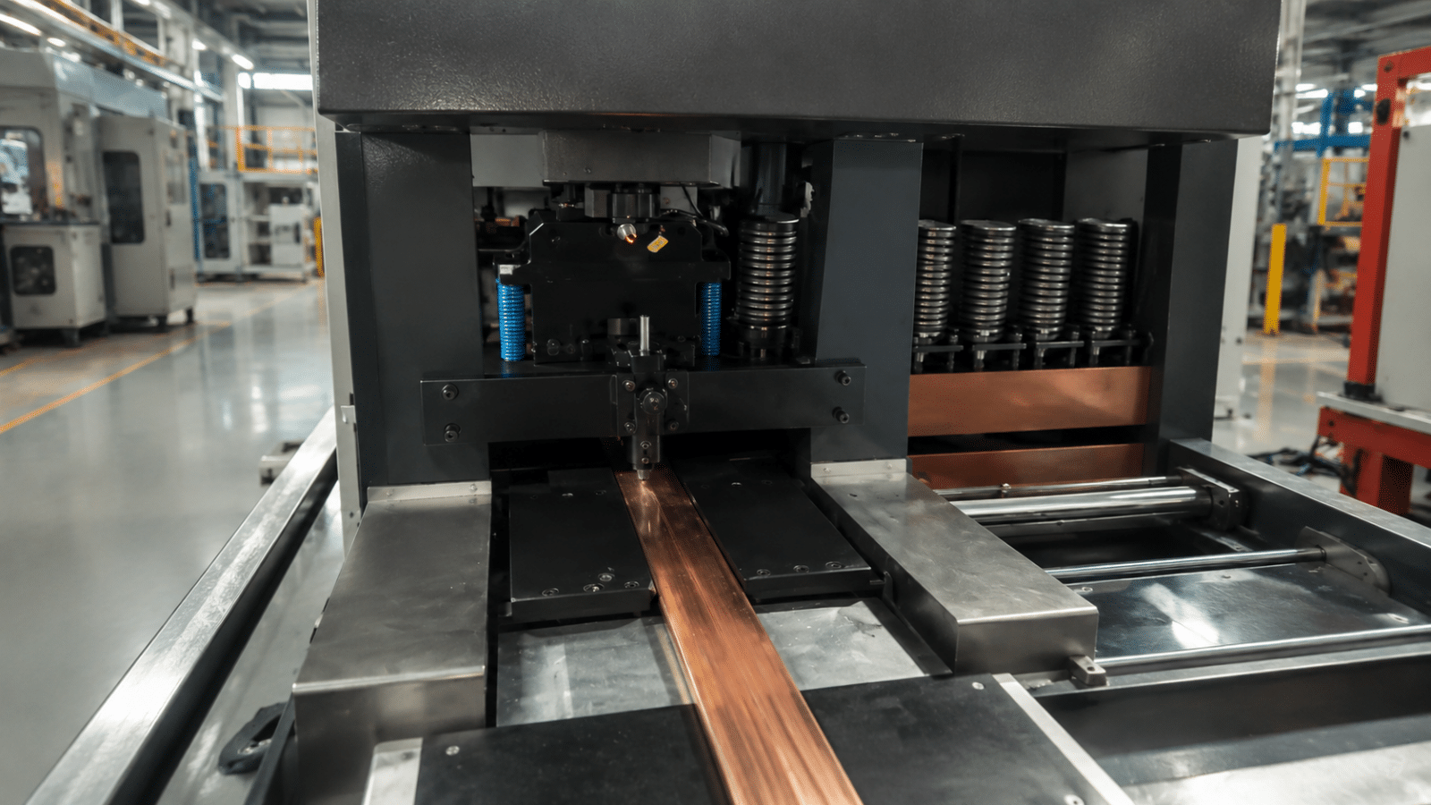
The customer selected our 600 kN class MX602K-8C with an eight-punch, one-shear die library, aimed not at a faster single punch stroke but at eliminating the two non-cutting blocks of time: die changing and re-clamping.
Eight-punch, one-shear die library: changing hole type without stopping. The library holds eight punching dies plus one shear, or seven punching dies plus one shear and one embossing die. The program selects the die by hole position, so a stop-and-swap operation becomes one line of program.
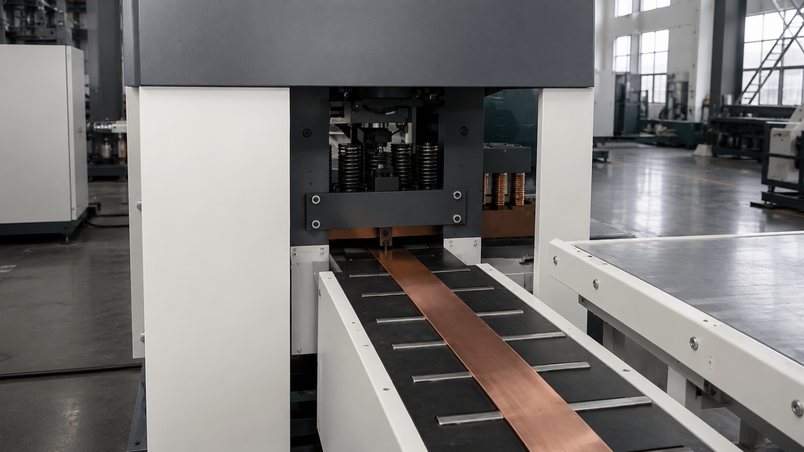
Six-axis servo with automatic re-positioning clamps: one clamping for the whole bar. The X axis travels 2000 mm at 75 m/min, the Y axis 960 mm and the Z axis 310 mm. Long bars are clamped once and the machine indexes the clamping point along the bar automatically until every hole and shear cut is complete, so re-clamping error disappears from the process.
Single-knife opposed shearing: no waste strip at the cut. The single-knife opposed shear (patent No. ZL201300804566.0) leaves nothing behind and produces a clean edge with no collapsed corner or burr, so lap faces need no hand grinding.
Accuracy held by the machine, not the operator. Punching accuracy is ±0.2 mm, positioning accuracy 0.10/500 mm and strike speed 120–150 per minute. The die frame is a single ductile iron body, which keeps the upper and lower die concentric over long service life. The machine ships with the Lijian busbar assistant design system (software copyright No. 0846802), which reflects program status on the man-machine interface in real time.
Components selected for maintainability. Hydraulic pump, solenoid valves, guides and lead screws, servo system and industrial computer are each offered in two brand tiers, selected for local spare-parts availability so maintenance is never locked to one source.
4. Implementation and Commissioning
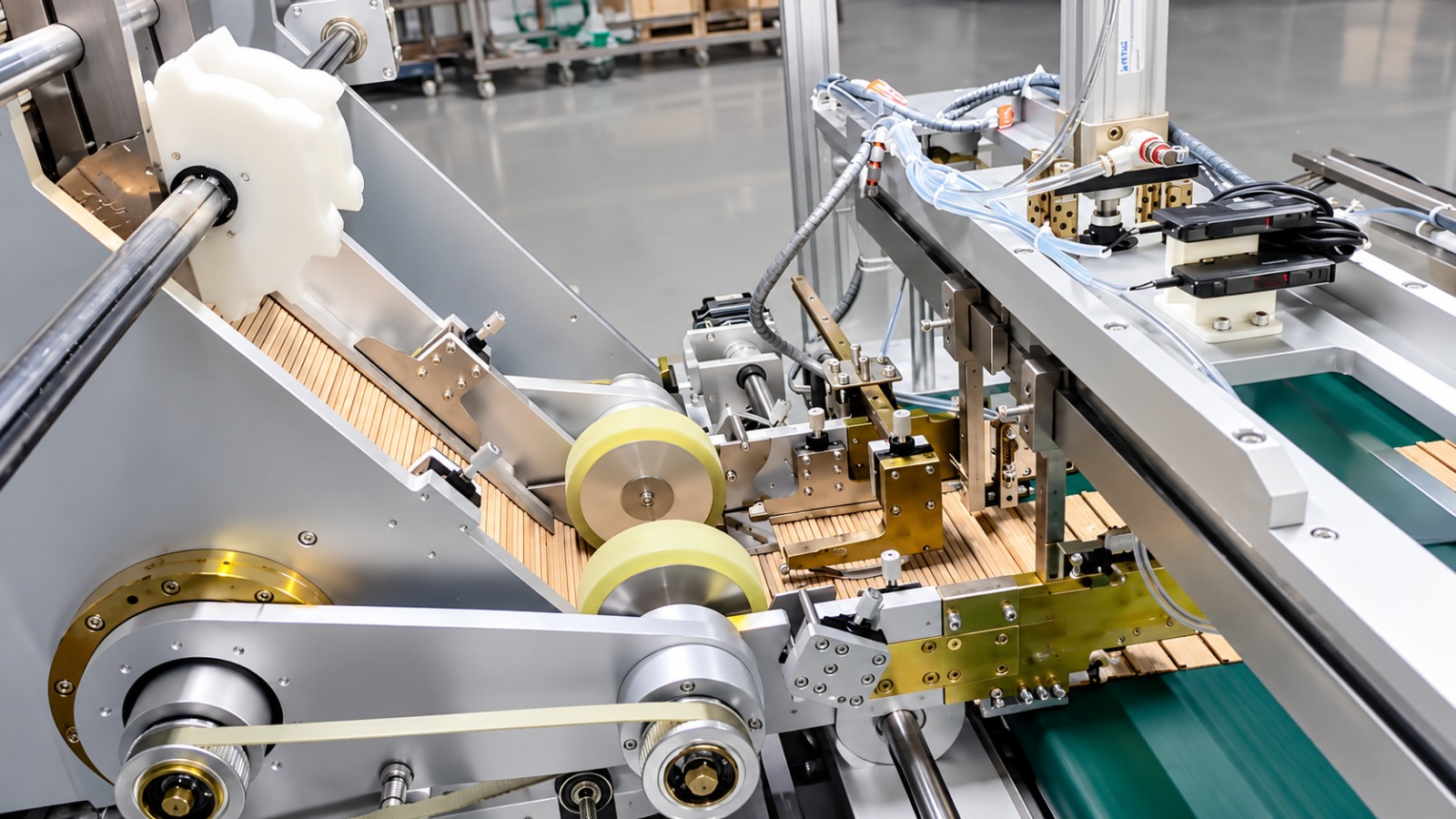
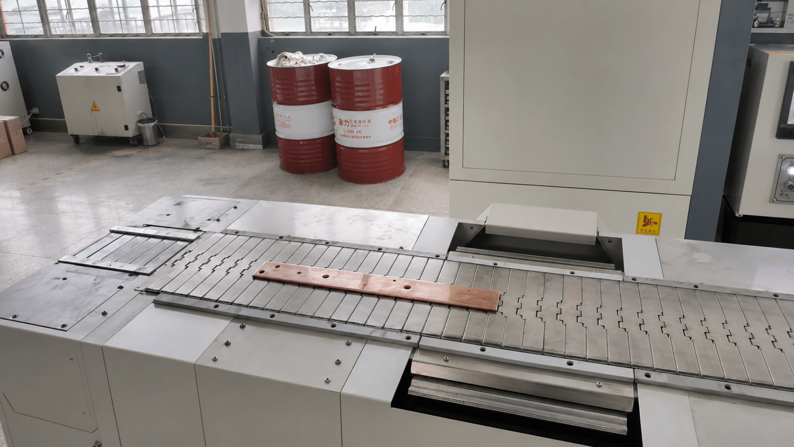
The machine was laid out as feeding table, die library, conveying device and servo control unit, tying into the existing raw-material and finished-goods areas so busbars never touch the floor.
Commissioning ran in three stages. Stage one, no-load verification: all six axes homed and limits checked, each die changed ten times with hole position measured, hydraulics calibrated to 600 kN, and shear clearance set to a baseline for medium-thickness copper. Stage two, trial production: 15×200 mm copper and 12×120 mm aluminum from current production were used to run ⌀4.3 mm, ⌀35 mm, slotted and square holes; positioning accuracy was spot-checked with gauge blocks over 500 mm; and the customer’s real compact substation drawing numbers were imported into the assistant design system to confirm the hole sequence matched what the machine produced. Stage three, handover: shear clearance, strike speed and die number for each material size were compiled onto process cards beside the machine, and two operators plus one maintenance technician were trained.
Two items needed the most adjustment. Shear blade clearance, because 15 mm copper and 3 mm aluminum need noticeably different clearances and the thin aluminum had shown edge roll-over, so a clearance table was rebuilt by thickness. And the clamp position for long-bar re-indexing, which initially sat too close to finished holes and was offset so the jaws cannot bruise a hole edge.
5. Acceptance Results
With the trial parts, process cards and operator training all confirmed, the machine was handed over against the following design and acceptance reference values.
| Parameter | Design and acceptance reference value |
| Nominal pressure | 600 kN |
| Maximum working size | 15×200 mm |
| Punching range | ⌀4.3–35 mm |
| Die library configuration | 8 punches + 1 shear (optional 7 punches + 1 shear + 1 embossing) |
| X axis maximum travel | 2000 mm |
| X axis positioning speed | 75 m/min |
| Y axis maximum travel | 960 mm |
| Z axis maximum travel | 310 mm |
| Punching accuracy | ±0.2 mm |
| Positioning accuracy | 0.10/500 mm |
| Strike speed | 120–150 times/min |
| Number of control axes | 6-axis |
| Machine size (L×W×H) | 1050×2950×1800 mm |
| Standard accessories | 8 sets of punching dies, 1 pair of shear blades, 1 set of maintenance tools |
6. Customer Feedback
“What used to worry us most was a drawing with many different hole diameters — half the day went into stripping dies and re-aligning dies. Now the hole type is selected in the program, a 15×200 copper bar is clamped once and runs end to end, and nothing needs grinding after the cut. The busbar shop finally schedules by drawing number instead of by die.” — Busbar shop manager at the customer
7. Summary and Next Steps
What this project actually removed were the two blocks of dead time in busbar processing: die changing and re-clamping. The eight-punch, one-shear die library turns a die change into a program instruction; six-axis servo control with automatic re-positioning clamps extends single-clamping coverage to a 2000 mm span; and single-knife opposed shearing eliminates the grinding that used to follow every cut. The 600 kN capacity and ⌀35 mm punching limit mean main busbars no longer need subcontracting, which puts delivery dates back under the customer’s control.
Looking ahead, the customer plans to import compact substation busbar drawings into the assistant design system in batches to build a library of program templates, cutting programming time for new drawings. They are also evaluating whether to link punching and shearing with the bending operation so both machines share one CNC programming package.
Get a Quote
- WhatsApp: +86-15958243831
- Email: sales@tranfovia.com
- Website: https://tranfovia.com/