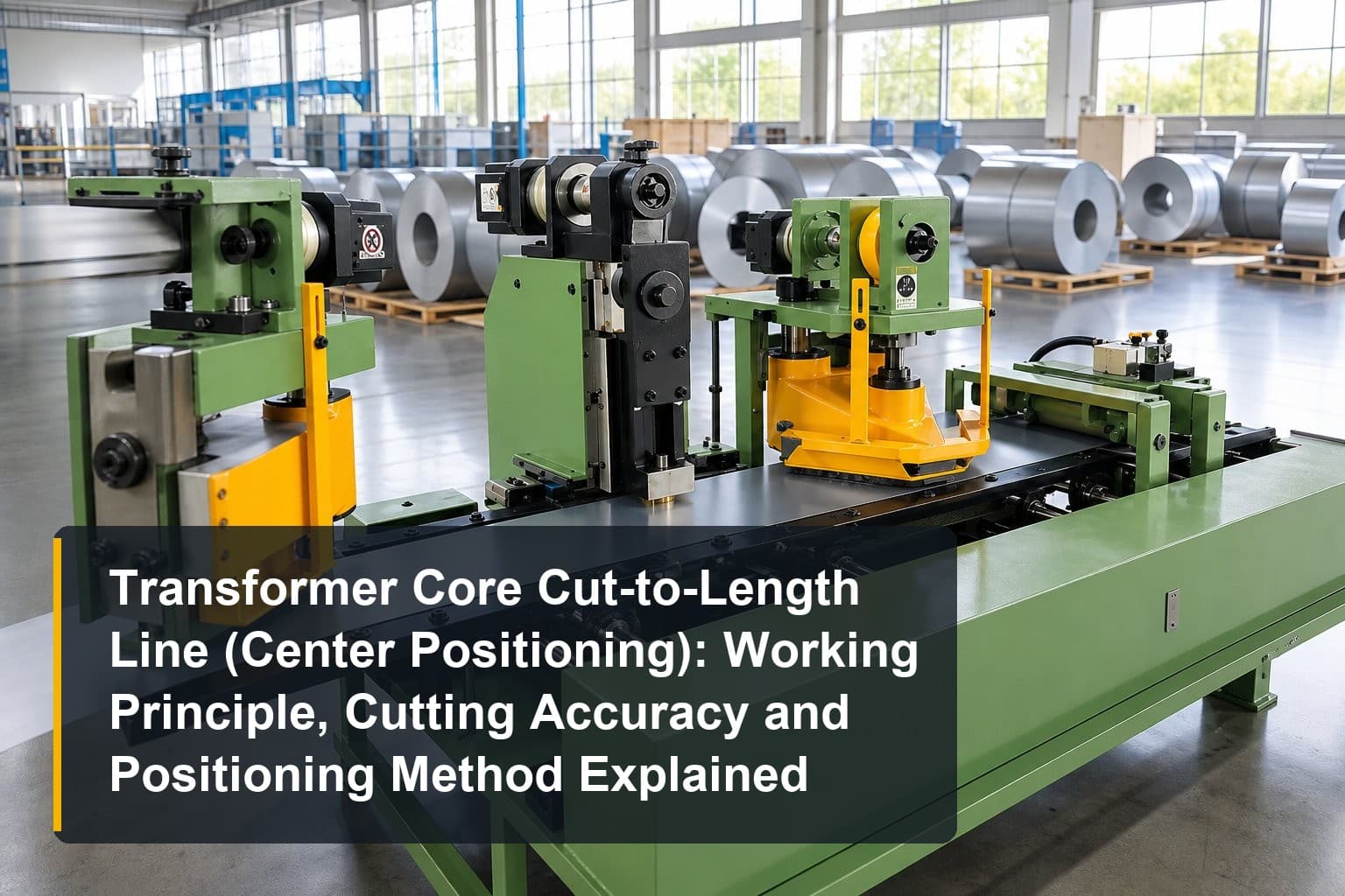
TL;DR:
- A transformer core cut-to-length line (center positioning) converts slit silicon steel strip into finished laminations through four synchronized stages: feeding, centering, punching/notching, and shearing.
- Cutting accuracy — length tolerance ±0.1 mm, angle accuracy ±0.025°, burr ≤0.02 mm — directly determines core loss, stacking factor, and assembly rework.
- Center referencing distributes strip width variation symmetrically, protecting both edge margins and improving material utilization on step-lap designs.
- Output quality depends on blade condition, feeding stability, and material handling; most defects are preventable with disciplined setup and maintenance.
How does a transformer core cut-to-length line (center positioning) work, and which specifications actually define its performance? This article explains the working principle and key stages of the machine, shows how cutting accuracy influences equipment performance, covers the process essentials of the positioning method and material utilization, and closes with the factors that shape output quality along with practical optimization tips.
Working Principle and Key Stages of a Transformer Core Cut-to-Length Line (Center Positioning)
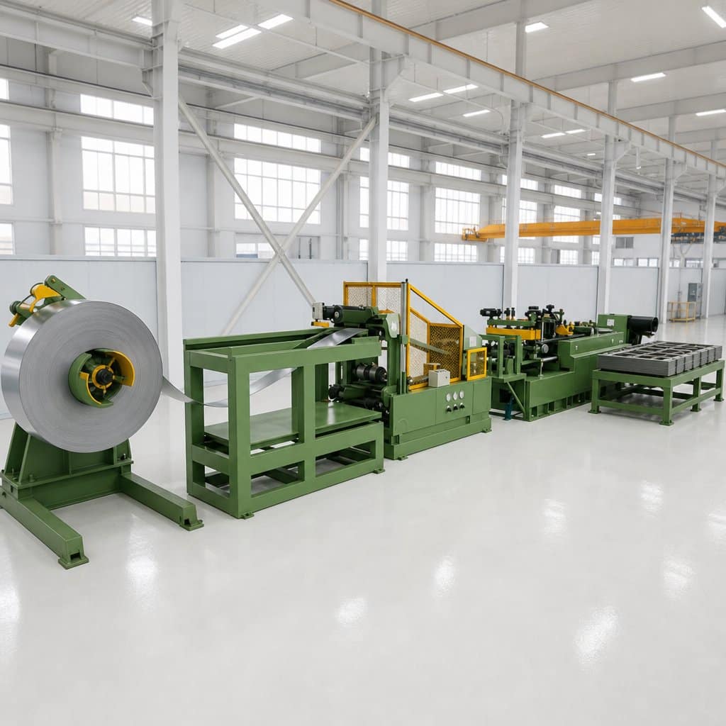
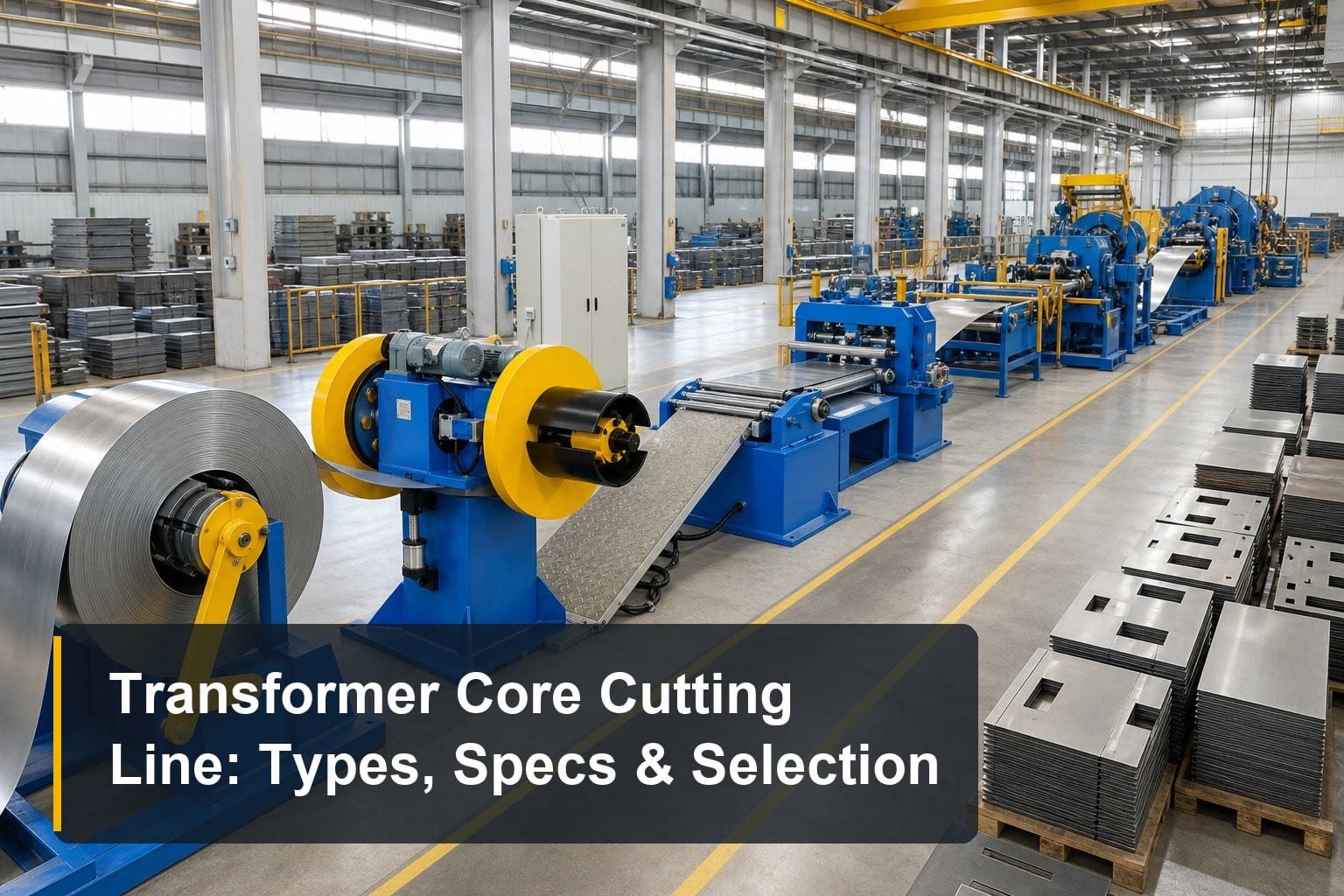
The working principle of a transformer core cut-to-length line (center positioning) is continuous, synchronized strip processing: silicon steel strip moves through the machine at up to 240 m/min while each station performs its task in a single pass. Four stages define the flow.
Stage 1: Decoiling and Strip Feeding
The process begins at the decoiler, where a coil of grain-oriented silicon steel — typically 0.18 to 0.35 mm thick — is unwound and fed into the line. A servo-driven feeding system meters the strip with encoder feedback, because every lamination length is ultimately defined by how precisely the strip advances. Any feed slip or speed fluctuation at this stage propagates directly into length error, which is why high-quality lines use closed-loop servo control rather than simple friction rollers.
Stage 2: Center Positioning and Guiding
Before any cutting happens, the strip passes through the centering unit — the defining feature of this machine type. Symmetrical guides reference the strip’s centerline rather than one edge, so lateral drift and width tolerance are distributed equally on both sides. The centering system continuously corrects strip position as it enters the punching and shearing zone, holding centerline deviation within roughly ±0.1 mm across the working width range of 40 to 600 mm depending on the model.
Stage 3: Punching, Notching, and Shearing
With the strip centered, CNC-controlled stations punch holes, cut V-notches, and shear the strip into laminations at programmed lengths — commonly 350 to 3,500 mm. Miter cuts at 45° for step-lap cores are made in the same pass, with cutting angle accuracy around ±0.025°. Because punching and shearing share one positioning reference, hole-to-edge and notch-to-edge dimensions stay consistent across the entire batch.
How Cutting Accuracy Influences Equipment Performance
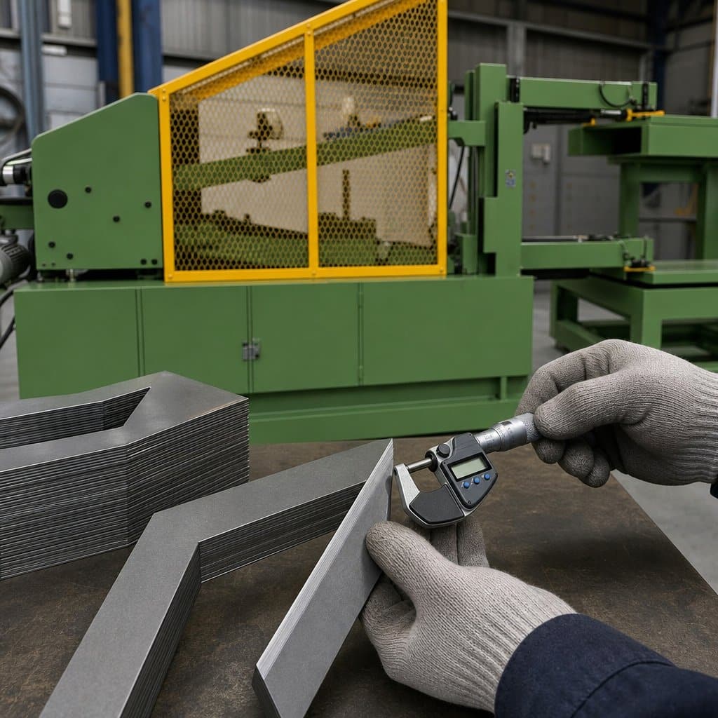
Cutting accuracy is the specification that separates a precision core cutting line from a simple shear. Three numbers define it — length tolerance, angle accuracy, and burr height — and each one maps to a measurable effect on transformer performance and production cost.
Length Tolerance and Stacking Factor
A length tolerance of ±0.1 mm sounds small, but laminations stack hundreds of layers deep. Systematic length error accumulates into uneven core packets, gaps at step-lap joints, and clamping problems during core assembly. Holding ±0.1 mm keeps the stacking factor high and the magnetic path continuous, which lowers no-load loss. This is the first figure to verify in any transformer core cut-to-length line (center positioning) specification sheet, and it should be a guaranteed production value, not a laboratory best.
Cutting Angle Accuracy and Step-Lap Joints
Modern energy-efficient cores use step-lap joints with 45° mitered laminations. Angle accuracy of ±0.025° ensures the mitered corners meet cleanly at the joint; angular error opens gaps that increase magnetizing current and audible noise. Because the joint effect multiplies across every corner of every core, even small angular drift shows up in routine no-load tests — which is why angle accuracy deserves the same scrutiny as length tolerance.
Burr Height and Interlaminar Insulation
Burr is the rolled edge left by the shear, and it must stay at or below 0.02 mm on grain-oriented steel. Excessive burr pierces the insulation coating between adjacent laminations, creating interlaminar short circuits that raise eddy-current loss and can produce local hot spots in service. Burr height is governed by blade sharpness, blade gap setting relative to strip thickness, and cutting speed — all machine-level factors that a quality line controls by design rather than by operator skill alone.
Positioning Method and Material Utilization Essentials
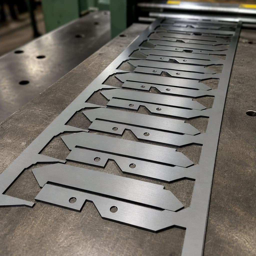
The positioning method determines not only dimensional consistency but also how much of each expensive silicon steel coil becomes a saleable lamination. Center positioning offers specific process advantages when it is set up correctly.
Why Center Referencing Protects Edge Margins
Slit strip always carries some width tolerance and camber from the slitting process. Edge-referenced machines push all of that variation to one side, which can shrink the insulation margin on the opposite edge below the design limit. Center referencing splits the variation symmetrically, so both edges keep their margins. For asymmetrical core designs where one edge must serve as the datum, a side-position core cutting line is the appropriate choice — the positioning method should follow the core drawing, not habit.
Nesting and Step-Lap Material Utilization
Material utilization on a cut-to-length line is driven by how efficiently lamination shapes nest along the strip. Step-lap designs with V-notches and 45° miters allow consecutive laminations to share cut lines, minimizing skeleton scrap. CNC programming that optimizes the cut sequence for each core design can raise utilization by several percentage points — significant when grain-oriented silicon steel is one of the most expensive materials in a transformer. Ask suppliers to demonstrate nesting for your actual lamination drawings.
Recipe Management and Changeover Discipline
Center positioning delivers its accuracy only when recipes are managed properly. Each core design should store strip width, guide opening, punch positions, and cut lengths as a named recipe, recalled at changeover rather than re-entered by hand. This eliminates the setup errors that cause first-article scrap and keeps positioning repeatability consistent across operators and shifts. Lines with automatic guide adjustment reduce changeover to minutes and remove a whole category of human error.
Factors That Influence Output Quality and Optimization Tips
Even a well-specified transformer core cut-to-length line (center positioning) will drift out of tolerance if blades wear, feeding becomes unstable, or material is mishandled. These factors are controllable, and the optimization tips below address each one.
Blade Condition and Gap Setting
Burr height is the earliest warning sign of blade wear. Measure burr at the start of each shift and track the trend rather than waiting for failures. Set the blade gap to roughly 5–10% of strip thickness — too tight accelerates wear, too loose guarantees burr. Keep matched blade sets for each thickness range, and record regrinding cycles so blade life becomes a planned maintenance item instead of a surprise stoppage.
Feeding Stability and Tension Control
Length accuracy depends on slip-free feeding. Keep feed rollers clean and correctly pressured, verify encoder calibration monthly, and watch for strip camber that can momentarily unload one side of the feed nip. Decoiler tension should be just enough to keep the strip flat — excessive tension stretches thin strip and shows up as length scatter. If length errors correlate with coil position rather than time, suspect the material before the machine.
Material Handling and Downstream Integration
Grain-oriented silicon steel loses its magnetic properties when bent sharply or struck, so output quality also depends on what happens after the cut. Smooth discharge onto a stacking table, gentle handling of finished lamination packets, and clean separation from the skeleton scrap all protect the steel you just cut accurately. Coordinating the line with a core stacking and turning table keeps laminations flat and ordered for the stacking team, closing the loop between cutting precision and core quality.
Frequently Asked Questions
What is the working principle of a center position core cutting line?
The line unwinds silicon steel strip, references it by the centerline, then punches, notches, and shears it into finished laminations in one continuous pass at up to 240 m/min. Center positioning distributes strip width variation symmetrically to both edges, which keeps lamination geometry balanced and protects insulation margins on symmetrical core designs such as EI and step-lap cores.
What cutting accuracy should a good line achieve?
A precision transformer core cut-to-length line (center positioning) should guarantee length tolerance of ±0.1 mm, cutting angle accuracy of ±0.025°, and burr height of ≤0.02 mm under production conditions. These values should be verified with test cuts on your own material grade before acceptance, because blade condition and setup influence the results.
When should I choose center positioning instead of side positioning?
Choose center positioning for symmetrical laminations — EI cores and step-lap designs — where both edges must keep equal margins. Choose side positioning when the core drawing defines one edge as the datum, as with asymmetrical or special-shaped laminations. Many factories run both, matching the positioning method to each core design.
How can I improve material utilization on my cutting line?
Focus on nesting and changeover discipline. Use CNC cut-sequence optimization so consecutive step-lap laminations share cut lines and minimize skeleton scrap, and store each core design as a named recipe to eliminate first-article setup scrap. Because grain-oriented silicon steel is expensive, even a few percentage points of utilization improvement repay quickly.
Summary
A transformer core cut-to-length line (center positioning) works by feeding silicon steel strip through synchronized decoiling, centering, punching, and shearing stages, and its real performance is defined by three numbers: ±0.1 mm length tolerance, ±0.025° angle accuracy, and ≤0.02 mm burr. Center referencing protects edge margins and supports high material utilization on step-lap designs, while blade care, feeding stability, and gentle handling keep output quality stable over years of production.
TRANFOVIA supplies center-position core cutting lines in 300, 400, and 600 mm width classes, with verified accuracy data and turnkey commissioning support. For model selection or a factory acceptance test on your material, contact TRANFOVIA today.
📞 +86-15958243831 📧 sales@tranfovia.com 💬 WhatsApp: https://wa.me/8615958243831 🌐 tranfovia.com
References
- IEC 60076-1:2011. Power transformers — Part 1: General. International Electrotechnical Commission. https://webstore.iec.ch
- IEEE Std C57.12.00-2015. IEEE Standard for General Requirements for Liquid-Immersed Distribution, Power, and Regulating Transformers. IEEE. https://standards.ieee.org
- ASTM A876/A876M. Standard Specification for Flat-Rolled, Grain-Oriented, Silicon-Iron, Electrical Steel. ASTM International. https://www.astm.org
- IEC 60404-8-7. Magnetic materials — Specifications for individual materials — Cold-rolled grain-oriented electrical steel. International Electrotechnical Commission. https://webstore.iec.ch
- Kulkarni, S. V., & Khaparde, S. A. (2004). Transformer Engineering: Design and Practice. Marcel Dekker.
- Georgilakis, P. S. (2009). Spotlight on Modern Transformer Design. Springer.