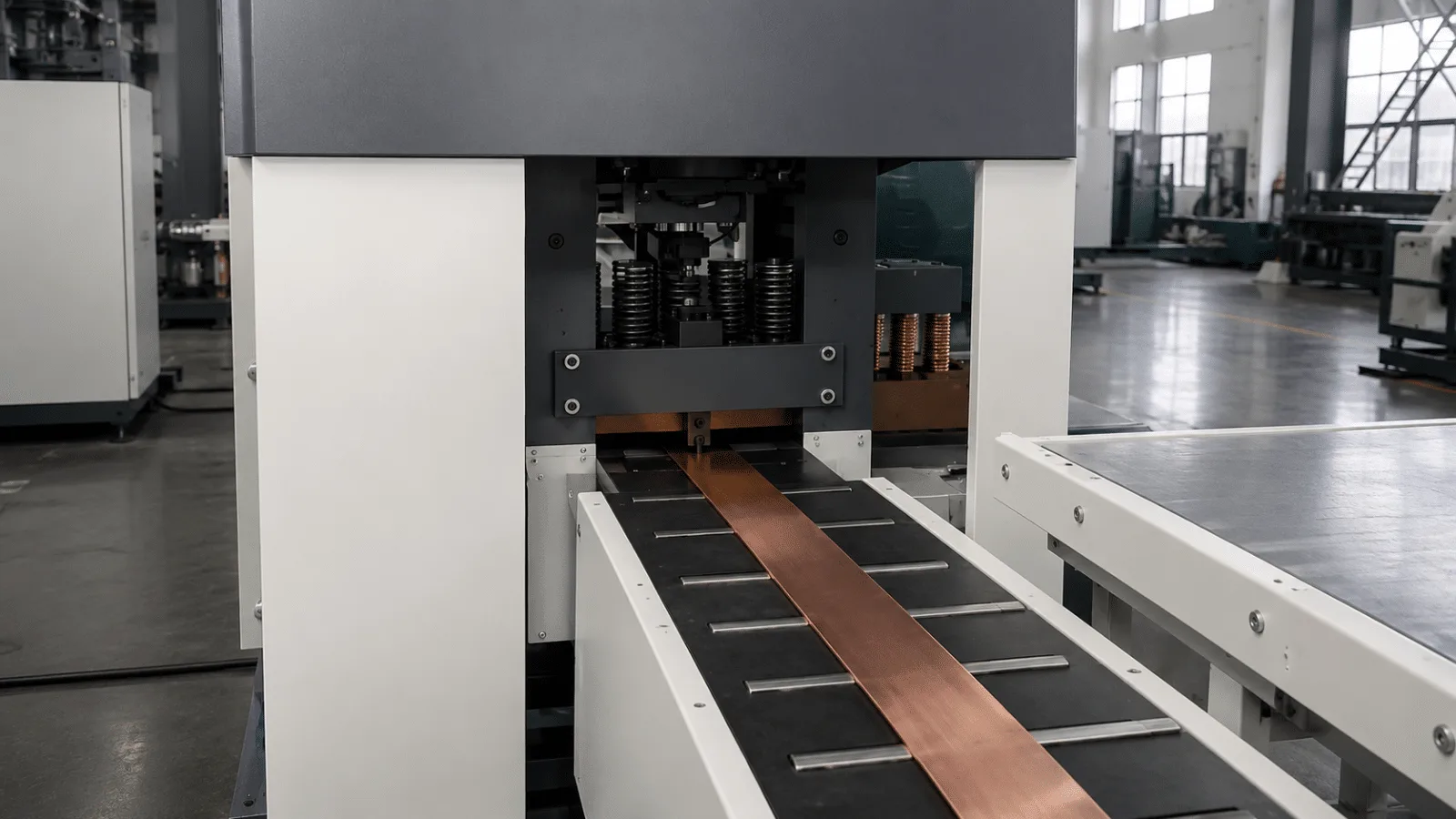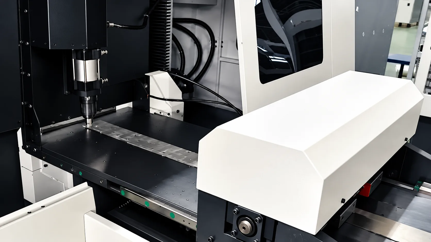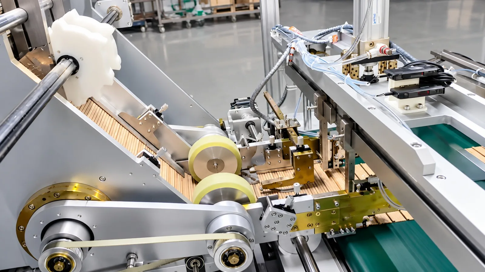

| Equipment | Transformer Core Cutting Line (silicon steel cut-to-length line) |
| Customer | A distribution transformer manufacturer in Rayong, Thailand (serving the Southeast Asian and South Asian markets) |
| Application | Automatic cut-to-length shearing of CRGO silicon steel coils and production of core laminations (yoke and limb pieces) |
Customer information has been anonymized; only region and industry attributes are retained. Performance figures are acceptance and typical-condition reference values and may vary depending on line configuration.
1. Customer Background
This customer, based in Rayong, Thailand, manufactures distribution transformers for the Southeast Asian and South Asian markets, producing oil-immersed and dry-type units rated up to 22 kV. The core is the first station on the transformer line and the origin of both no-load loss and noise. As local grid upgrades and industrial distribution orders grew, the previous setup — a single cut-to-length shear with manual measurement and manual sorting — could no longer hold either the delivery tempo or the mix of widths and lengths the order book demanded. After evaluating several suppliers, the customer selected our silicon steel cutting line; equipment of the same series has been delivered to customers in India, the Middle East and South America.
2. Industry Pain Points
A transformer core is built by stacking yoke and limb laminations alternately, so the length error and the end angle of every single piece accumulate into the finished core: joints that do not line up raise no-load loss and noise, while burrs create short-circuit paths between laminations. The customer’s single-machine, manual method produced four recurring problems:
Length verified by hand. Sample measurement left length variation accumulating batch by batch, so stacked cores had misaligned joints that had to be reworked by hand.
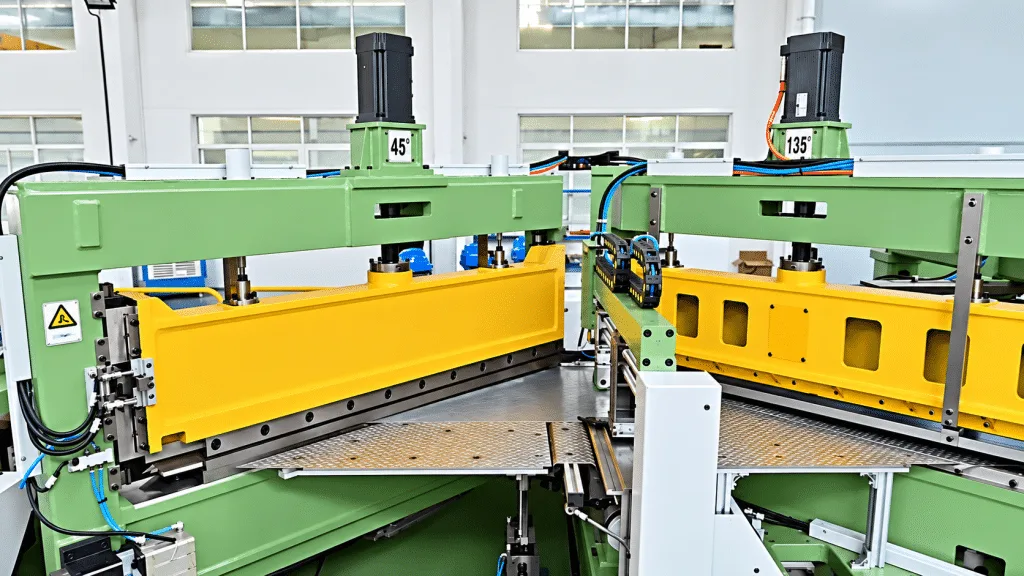
Mitre angles set by trial cuts. The 45° and 135° mitre ends of limb and yoke pieces depended on manual knife setting and trial cuts. Angle consistency was poor and the air gap at the joint ran wide.
Unstable burr control. As the blade wore, burr size increased, so inter-lamination short circuits appeared together with a loss of stacking factor — pushing core loss and temperature rise upward.
Slow changeovers and heavy manual work. Widths and lengths changed frequently, and the cut pieces still had to be sorted and carried by hand, with mixing and edge damage a constant risk.
3. Solution
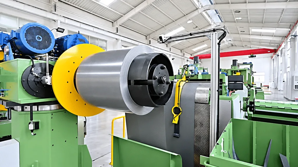
We configured a complete line from coil loading to sorting and stacking: automatic decoiler → buffer feed → 45°/135° dual shear heads → servo cut-to-length feed → sorting and stacking table, all coordinated by a PLC and HMI. The design principle was to move core lamination accuracy from measured-by-hand to cut-by-program:
- Mitre ends cut in one pass. The two shear heads are arranged at 45° and 135°, so a single stroke performs both the cut-to-length shear and the mitre end forming, with an angular accuracy of ±0.025°. Limb and yoke pieces can be stacked alternately as they come off the line.
- Length held by a servo loop. Servo feeding with closed-loop length control holds cutting length to ±0.1 mm, so piece length no longer drifts with the batch or with the operator.
- Stable burr control. Cutting burr is held to ≤0.02 mm, with blade clearance set according to material thickness, sharply reducing the risk of inter-lamination shorts and the associated loss of stacking factor.
- One line, multiple specifications. Silicon steel thickness 0.18–0.35 mm, sheet width 60–600 mm and cutting length 500–3500 mm are all handled on the same line, covering cores from distribution transformers up to medium power transformers.
- A tempo that no longer bottlenecks. The line feeds at up to 240 m/min and is interlocked with the decoiler and the loop pit, so the first station on the transformer line stops being the constraint for the whole plant.
- Sorting and stacking instead of manual handling. Cut laminations are sorted and stacked automatically by program, cutting sorting labour, edge damage and the risk of mixing specifications.
- Changeover from the screen. Decoiler tension, feed length, shear angle and stacking pattern are all set from the same HMI, so switching to a new lamination size is a parameter entry rather than a tooling reset. The decoiler, loop buffer and shear heads are interlocked through one controller, so coil changes can be prepared while the line finishes the current batch.
On the old layout, every change of sheet width or piece length meant re-setting the shear by hand and re-checking the first pieces before the batch could run. On this line the first piece is already to length, and the pieces that follow match it.
4. Implementation and Commissioning
After the line arrived by sea, TRANFOVIA engineers worked with the customer’s equipment and process teams through a three-step on-site commissioning. First, we verified foundation levels, the power supply (380 V three-phase) and the pneumatic circuits, then ran the decoiler, shear heads and stacking table empty. Second, with the customer’s main specification we threaded material through the line, tuned the feed acceleration and deceleration curve, the cutting length and the angle of both shear heads item by item, and synchronized the line tempo. Third, we produced trial limb and yoke pieces against the acceptance criteria of the technical agreement, checked length, angle and burr batch by batch, and trained the customer’s operators and maintenance crew while delivering English operation and maintenance manuals.
5. Acceptance Results
The line was verified item by item against the technical agreement during commissioning. Key indicators (design and acceptance reference values; actual figures depend on the configured line):
| Indicator | Value / Result |
| Material | Cold-rolled grain-oriented silicon steel (CRGO), 0.18–0.35 mm |
| Sheet width | 60–600 mm |
| Cutting length | 500–3500 mm |
| Feeding speed | Up to 240 m/min |
| Cut-to-length accuracy | ±0.1 mm |
| Cutting angle accuracy | ±0.025° |
| Cutting burr | ≤0.02 mm |
| Shear head angles | 45° / 135° |
| Total motor power | 34–37 kW |
Two changes were most visible to the customer: piece length and end angle are now guaranteed by the program, so the stacked core closes with its joints aligned on the first pass; and the first station on the transformer line moved from manual measurement plus manual sorting to continuous shearing with automatic stacking.
6. Customer Feedback
“We used to have people watching every piece — measuring the length, checking the mitre angle. Now the parameters are set and the whole batch comes out the same. The joints close up much better during stacking, and rework has clearly dropped.” — Customer core shop supervisor (at acceptance)
7. Summary and Next Steps
For transformer manufacturers, competition in cores is no longer about whether a lamination can be cut, but about piece-length consistency, end-angle accuracy and how fast specifications can be switched. This cutting line integrates decoiling, cut-to-length shearing, mitre end forming, and sorting and stacking into one continuous flow — moving core accuracy from manual measurement to machine parameters.
To configure a line around your core specification range, sheet widths and tempo targets, contact the TRANFOVIA technical team for a proposal.
- WhatsApp: +86-15958243831
- Email: sales@tranfovia.com
- Website: https://tranfovia.com/