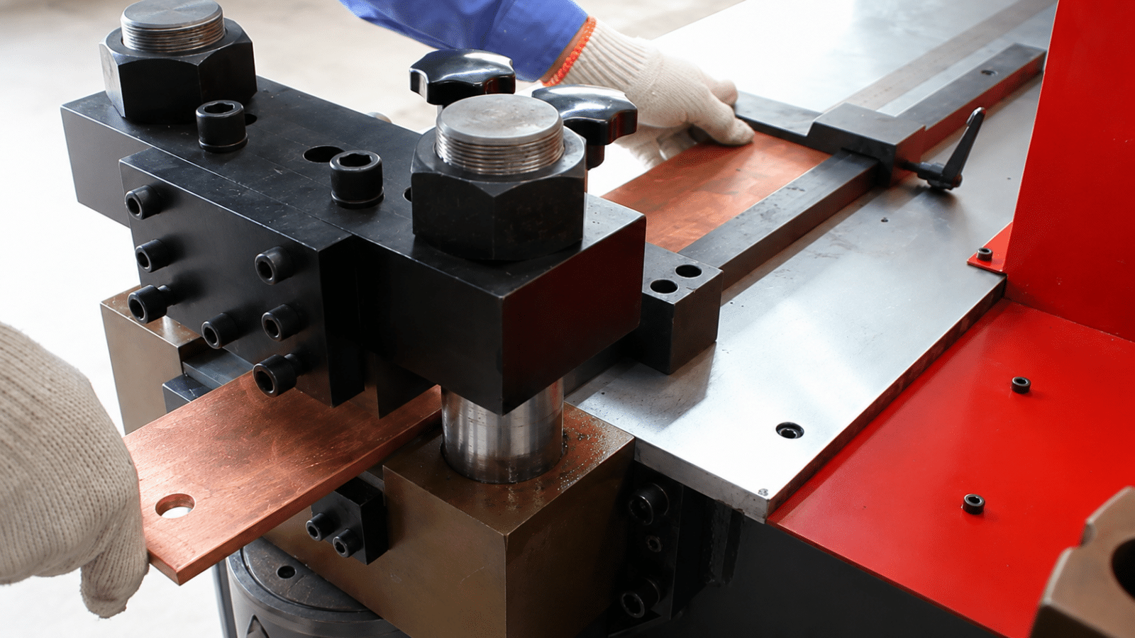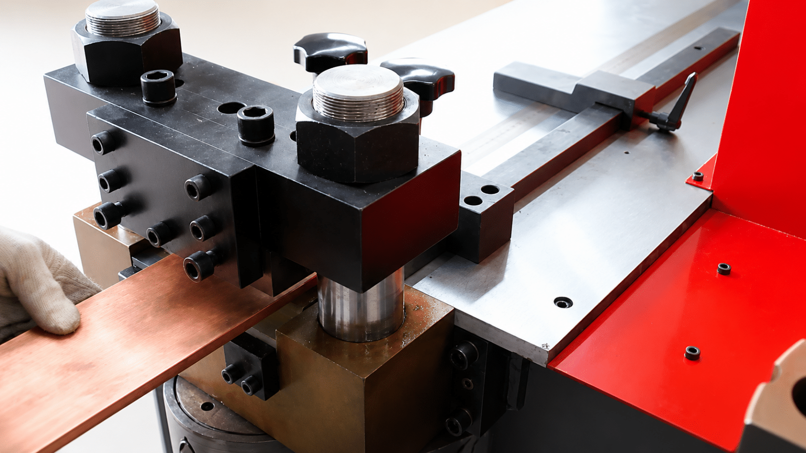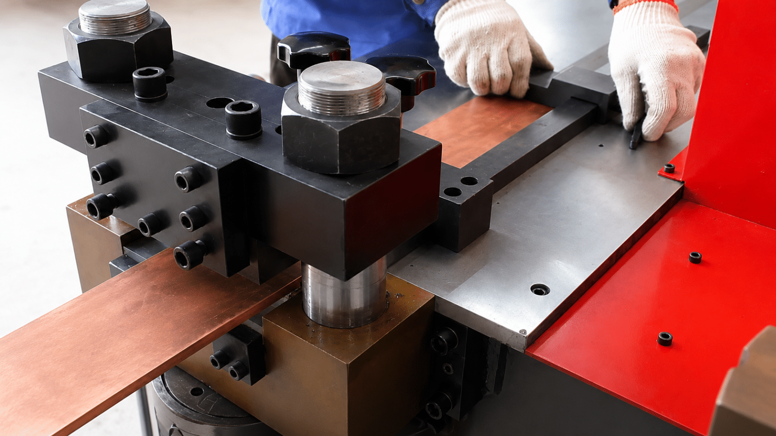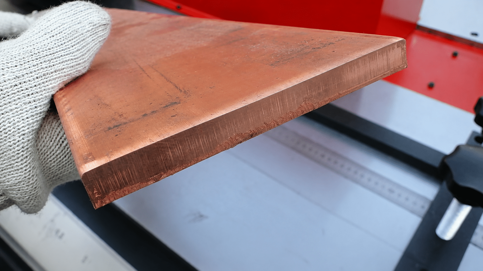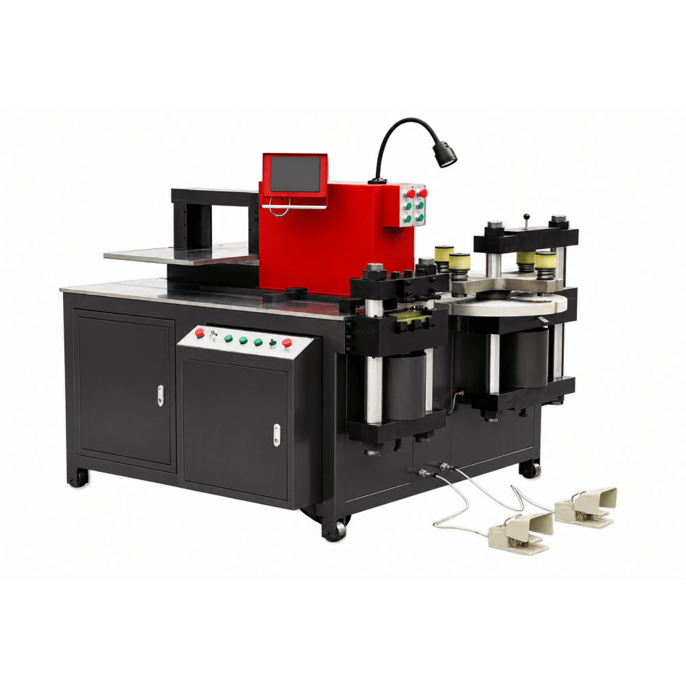
The TRANFOVIA 503 Series Hydraulic Busbar Processing Machine is designed for transformer and electrical equipment manufacturers whose busbar production exceeds the 12 × 160 mm capacity of the 303 Series and requires processing up to 16 × 200 mm.
With a nominal force of 500 kN and a punching range of Φ4.3–32 mm, the 503 Series integrates cutting, punching and bending in one multifunction machine platform. C-series and E-series configurations are available according to workstation organization, punching flexibility and bending-control requirements.
| Maximum Busbar Size 16 × 200 mm |
Nominal Force 500 kN |
Punching Range Φ4.3–32 mm |
Main Functions Cut / Punch / Bend |
The main reason to move from the 303 Series to the 503 Series is processing capacity. If regular production exceeds the 12 × 160 mm range but remains within 16 × 200 mm, the 503 Series is the appropriate capacity class to evaluate.
If regular busbars are wider than 200 mm or require the 16 × 260 mm class, the 803 Series should be evaluated instead.
| Selection Point | 303 Series | 503 Series |
| Maximum Busbar Size | 12 × 160 mm | 16 × 200 mm |
| Nominal Force | 350 kN | 500 kN |
| Punching Range | Φ4.3–25 mm | Φ4.3–32 mm |
| Choose When | Regular busbars stay within 12 × 160 mm | Regular busbars exceed 303 capacity but stay within 16 × 200 mm |
All main 503 configurations share the same 500 kN nominal force and 16 × 200 mm maximum busbar size. The model decision therefore depends on workstation organization, punching flexibility and bending-control requirements.
| Configuration | Three Stations Simultaneously | Rotary Punching | Digital Bending Control | Recommended For |
| 503C-1 | No | Standard punching | No | Basic 16 × 200 mm cutting, punching and bending |
| 503C-3 | Yes | Standard punching | No | Simultaneous three-station production |
| 503E-3 | Yes | Yes | No | Frequent punching and multi-process production |
| 503E-3-S | Yes | Yes | Yes | Repeated bending with digital angle control |
The 503C-1 is suitable when the factory needs the 16 × 200 mm capacity but does not require the cutting, punching and bending stations to operate simultaneously.
The 503C-3 keeps the same 500 kN force, 16 × 200 mm maximum busbar size and Φ4.3–32 mm punching range, but allows the three workstations to operate simultaneously.
The upgrade from 503C-1 to 503C-3 is therefore a production-flow decision, not a capacity upgrade.
The 503E Series is intended for workshops that require 16 × 200 mm / 500 kN capacity together with rotary punching, a double-worktable arrangement and simultaneous three-station operation.
For transformer factories processing many busbar designs, hole requirements can change between different profiles and diameters. The rotary punching arrangement on the 503E Series allows multiple punching dies to be prepared on the machine, reducing repeated die-changing interruptions when specifications vary.
Choose the 503E-3 when rotary punching, double worktables and simultaneous three-station operation are required, but digital bending angle control is not necessary.
The 503E-3-S keeps the same 500 kN and 16 × 200 mm processing capacity while adding digital bending angle control. It is more suitable when the same bending angles or busbar geometries recur across production batches.
| Parameter | 503C-1 | 503C-3 |
| Nominal Force | 500 kN | 500 kN |
| Maximum Busbar Size | 16 × 200 mm | 16 × 200 mm |
| Punching Range | Φ4.3–32 mm | Φ4.3–32 mm |
| Worktable Size | 1500 × 1200 mm | 1500 × 1200 mm |
| Machine Dimensions | 1750 × 1350 × 1250 mm | 1750 × 1350 × 1250 mm |
| Machine Weight | 1600 kg | 1750 kg |
| Digital Bending Angle Control | No | No |
| Three Stations Simultaneously | No | Yes |
| Parameter | 503E-3 | 503E-3-S |
| Nominal Force | 500 kN | 500 kN |
| Maximum Busbar Size | 16 × 200 mm | 16 × 200 mm |
| Punching Range | Φ4.3–32 mm | Φ4.3–32 mm |
| Main Worktable | 1600 × 1400 mm | 1600 × 1400 mm |
| Second Worktable | 1020 × 500 mm | 1020 × 500 mm |
| Machine Dimensions | 1920 × 1550 × 1500 mm | 1920 × 1550 × 1500 mm |
| Machine Weight | 1870 kg | 1900 kg |
| Digital Bending Angle Control | No | Yes |
| Three Stations Simultaneously | Yes | Yes |
The cutting station shears copper and aluminum busbars to the required length using a double-column shearing structure.
The punching station produces connection holes and other specified profiles. The listed punching range for the 503 Series is Φ4.3–32 mm.
The bending station supports flat and vertical forming for transformer busbar routing and connection geometry.
With the corresponding tooling, the machine can also support U-bending, embossing, flattening, cable lug pressing and twisting.
| Series | Nominal Force | Maximum Busbar Size | Punching Range | Typical Selection |
| 303 | 350 kN | 12 × 160 mm | Φ4.3–25 mm | Standard transformer busbar sizes |
| 503 | 500 kN | 16 × 200 mm | Φ4.3–32 mm | Larger and thicker busbars |
| 803 | 800 kN | 16 × 260 mm | Φ4.3–36 mm | Wide heavy-duty busbars |
If the largest production busbar already exceeds 12 × 160 mm, moving to a higher 303 configuration will not increase the basic size range. The 503 Series is the capacity upgrade for busbars up to 16 × 200 mm.
The 503 Series is suitable for transformer factories processing copper and aluminum busbars that require a larger capacity than the 303 Series. Typical work includes preparing cut, punched and bent busbar connections for transformer terminals and other electrical connection points where the required dimensions remain within 16 × 200 mm.
The listed maximum processing size is 16 × 200 mm.
The listed punching range is Φ4.3–32 mm, subject to the selected punching dies and hole geometry.
Choose the 503 Series when regular production exceeds the 12 × 160 mm capacity of the 303 class but remains within 16 × 200 mm.
Both have the same 500 kN and 16 × 200 mm capacity. The 503C-3 allows the three workstations to operate simultaneously, while the 503C-1 does not.
Choose the 503E Series when rotary punching, double worktables and simultaneous three-station production are important to the workshop.
Both have the same basic processing capacity. The 503E-3-S adds digital bending angle control.
Provide busbar material, maximum width and thickness, hole requirements, bending drawings, production arrangement and factory power supply.