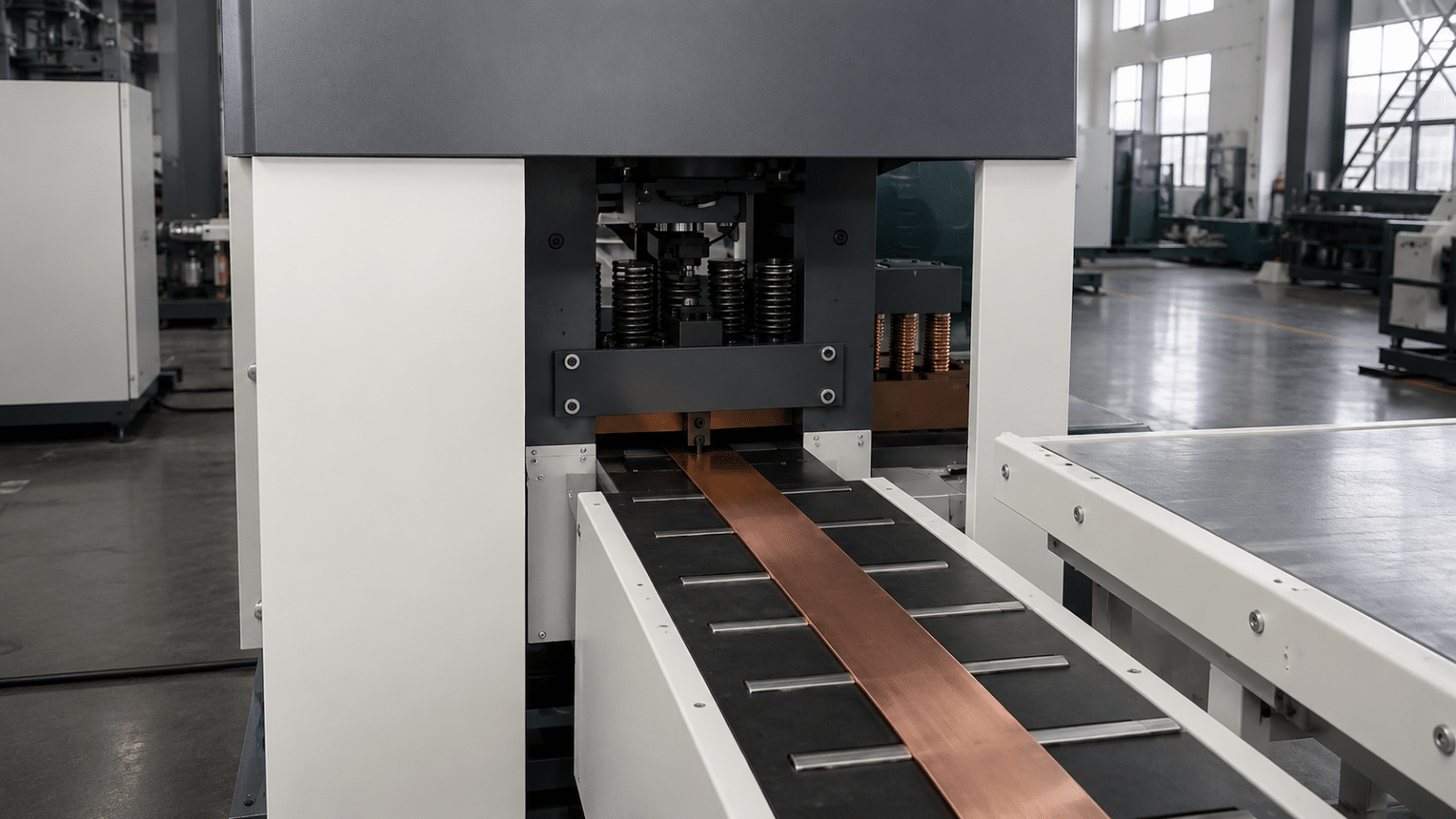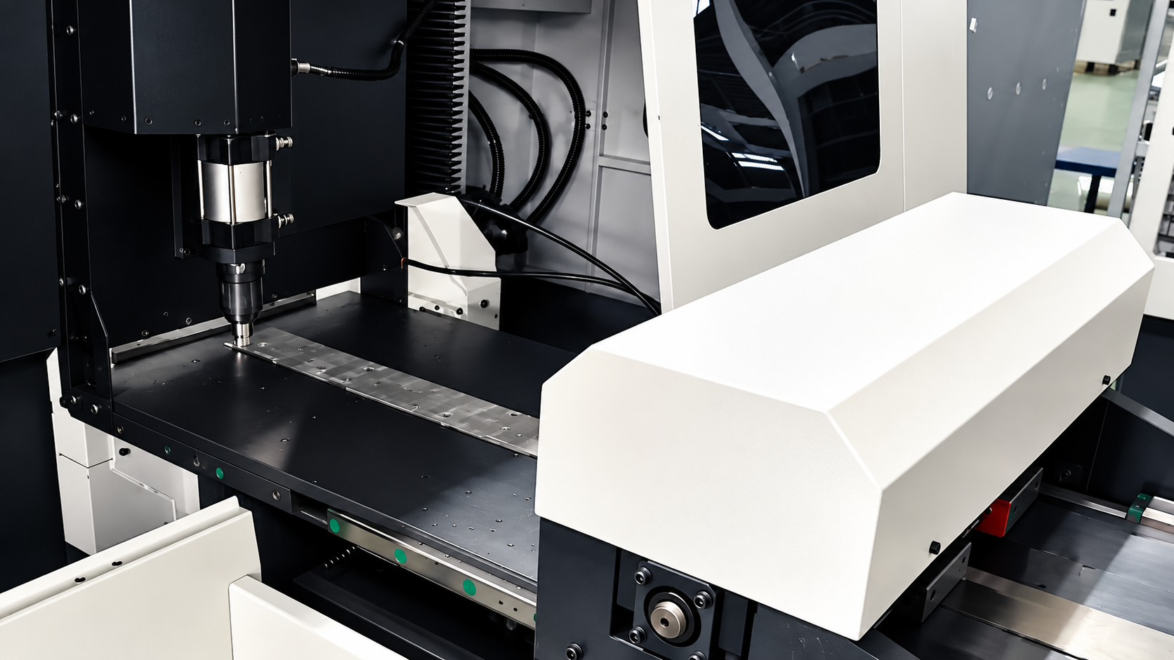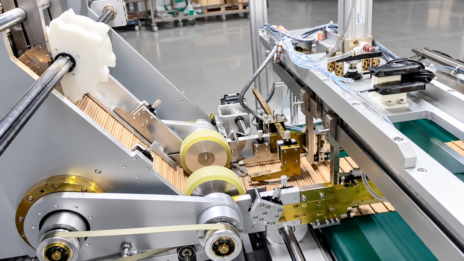
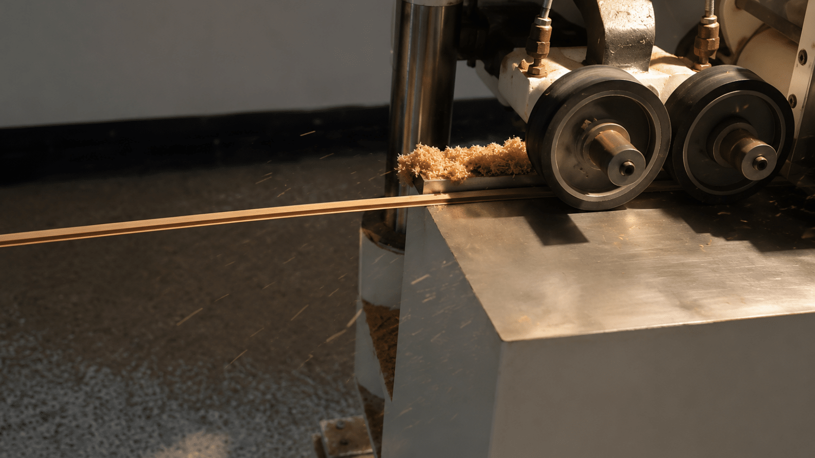
| Equipment | Pressboard Strip Rolling and Chamfering Machine |
| Customer | A distribution and dry-type transformer manufacturer in Surabaya, East Java, Indonesia (in-house insulation parts shop) |
| Application | Rolling 1.5–15 mm insulation pressboard strips to an 8–10% compression ratio and chamfering both longitudinal edges into the required R profile for spacer strips and cooling-duct strips |
1. Customer Background
The customer builds distribution transformers and dry-type transformers in Surabaya and supplies its own winding spacers and cooling-duct strips. Strips are cut to width first, then still have to be rolled to a specified compression ratio and have both longitudinal edges rounded into an R profile before they can go to assembly. Rolling and chamfering used to run on two separate machines. Several thousand strips pass through the shop in a day, thin strips picked up press marks at the second clamping, the R edges were dressed by hand on an abrasive belt, and assembly kept returning parts. After the expansion the customer decided to merge both operations into one pass.
2. Industry Pain Points
Cutting to width is not the hard part. The hard part is holding the compression ratio and the R profile on every single strip. The previous practice had five problems:
- Two machines, two clampings: strips were rolled first and chamfered afterwards, with handling and floor transport in between, and a 1.5 mm strip often picked up press marks at the second clamping, so loading itself became a source of scrap;
- R edges dressed by hand: the radius followed the operator’s feel on an abrasive belt, so R varied within one batch, edges frayed and delaminated, and neighbouring insulation parts were scored during assembly;
- Compression ratio not controllable: the 8–10% reduction had no setting to work from, the result depended on experience, strip thickness varied, and the deviation accumulated into winding height;
- The two sections did not stay in step: rolling and chamfering were each speed-controlled, so strips either piled up between the units or were pulled apart, most visibly on 10 mm narrow strips;
- Every size change was a reset: with 1.5 mm and 15 mm sheet and 10 mm to 100 mm widths running in mixed batches, the rolling rollers and cutter positions were re-set each time, and setting took longer than machining.
3. Solution
The customer chose the Pressboard Strip Rolling and Chamfering Machine. The objective was not output but merging rolling and chamfering into a single pass and turning both the compression ratio and the R profile into values that can be set and checked:
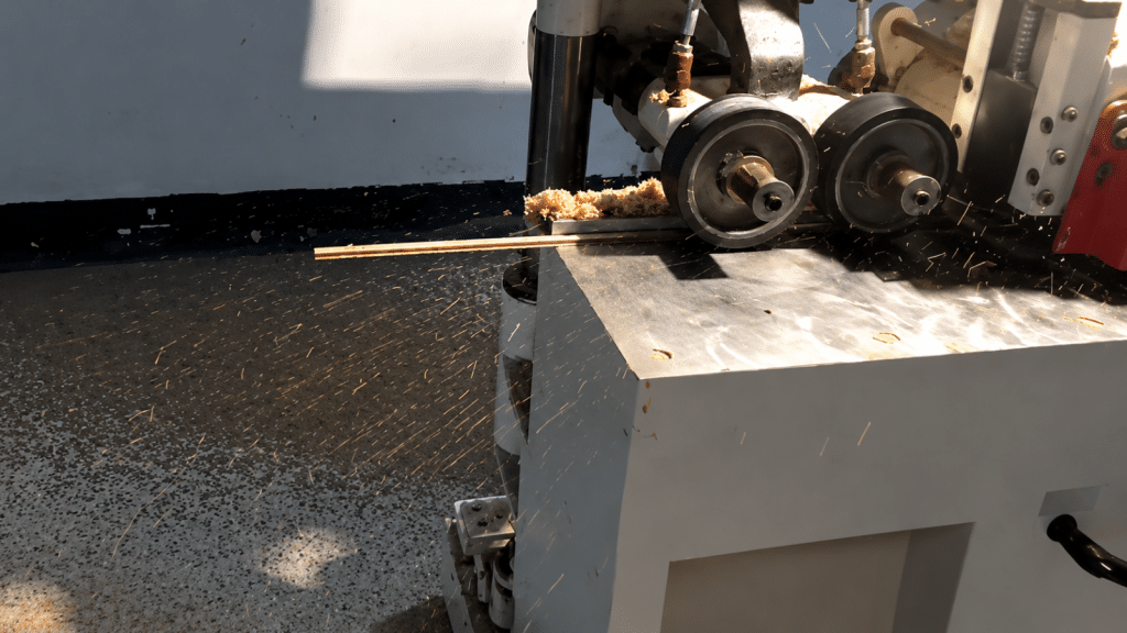
- Rolling and R chamfering in one pass: the rolling rollers and the chamfering cutter shaft work in the same pass, so one clamping completes both the rolling and the rounding of both longitudinal edges, and the floor transport in between disappears;
- Maximum rolling force of 50 T: the rolling section compacts the pressboard at the set force, and every thickness from 1.5 to 15 mm runs through the same roller set;
- 8–10% compression ratio, controlled: rolling reduction is set against the incoming strip thickness and checked on the outgoing strip with a micrometer, so the ratio no longer depends on feel;
- Customer-specified R profile: the R dimension and the tooling are configured around the approved strip drawing, and a size change means a different tooling set while both edges are rounded in one pass;
- Milling cutter speed of 6000 r/min: high-speed milling leaves a clean chamfer face, so edges do not fray or delaminate and no dressing is needed before assembly;
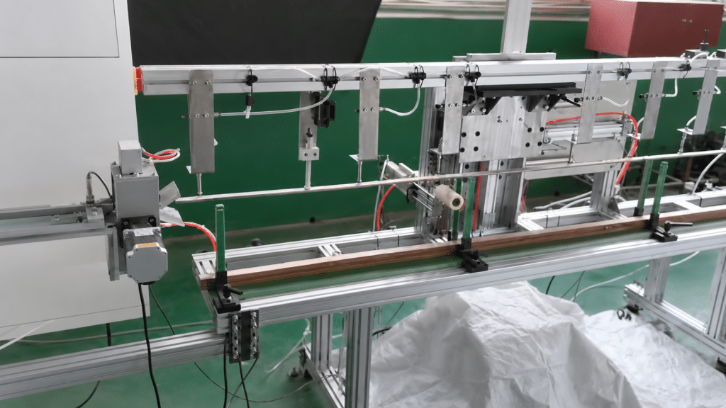
- Feed speed 4–15 m/min, stepless: rolling and chamfering share one frequency-conversion feed train, so the two sections stay synchronized by construction and narrow strips are not pulled apart;
- Minimum processing length 700 mm, separate line configuration: the machine runs as a stand-alone unit or is installed after the existing strip-cutting or shaping operation, which keeps the process sequence flexible.
4. Implementation and Commissioning
TRANFOVIA engineers worked through commissioning with the customer’s insulation shop in three steps. First, tooling and rolling parameters against the drawings: the R dimensions, the 10–100 mm strip widths and the 1.5–15 mm thickness range of four strip types were checked, the rolling reduction and tooling set were fixed for each type, and a size-change reference table was issued. Second, site preparation and dry running: the machine was levelled and anchored, power and the dust-collection duct were connected, and the feed was run through the full 4–15 m/min range while roller-to-cutter synchronization, the guards and the emergency stop were verified. Third, trial rolling and training: the customer supplied 1.5 mm, 3 mm, 6 mm, 10 mm and 15 mm pressboard, incoming and outgoing thickness were measured to confirm the compression ratio, the R profile was checked against a gauge, edges were inspected for burrs, and the operators were trained on tool changing, rolling-reduction setting, feed-speed adjustment and dust-collector cleaning using the English manual.
5. Acceptance Results
The machine was accepted item by item against the technical agreement, with the key parameters below (design and acceptance reference values, subject to configuration):
| Item | Design and acceptance reference |
| Strip thickness | 1.5–15 mm |
| Strip width | 10–100 mm |
| R profile | Customized to the customer drawing |
| Milling cutter speed | 6000 r/min |
| Feeding speed | 4–15 m/min, stepless frequency conversion |
| Minimum processing length | 700 mm |
| Maximum rolling force | 50 T |
| Pressboard compression ratio | 8–10% |
All five thicknesses ran back to back on the trial day: the 1.5 mm strips came off without press marks or wavy edges, the 15 mm strips landed inside the 8–10% compression window, the R profile of all four strip types fitted the gauge on both edges, and the edges showed no fraying or delamination, so strips went straight to assembly.
6. Customer Feedback
“We used to roll on one machine and chamfer on another, move the strips twice, and thin strips took press marks. Now one pass does both, the R profile fits the gauge, and assembly stopped rejecting parts. Rolling reduction is set from the thickness, so thin and thick batches no longer need a new feel for it.” — Insulation shop supervisor, acceptance stage
7. Summary and Next Steps
The value of the Pressboard Strip Rolling and Chamfering Machine is not throughput but merging two operations into one: the rolling rollers and the chamfering cutter shaft work in the same pass, one clamping carries the strip through both, the 50 T rolling force with an 8–10% ratio makes the reduction settable and verifiable, the R profile is built around the customer drawing with a 6000 r/min milled finish, and thicknesses and widths can be mixed without changing machines.
Next, the customer plans to turn the size-change reference table into an illustrated chart kept at the machine and to schedule production by strip width so tooling changes drop further. It is also evaluating extending the line to take short strips straight from the cutting operation. For a pressboard strip rolling and chamfering configuration, contact the TRANFOVIA technical team.
- WhatsApp: +86-15958243831
- Email: sales@tranfovia.com
- Website: https://tranfovia.com/