| Equipment | Corrugated Fin Automatic Welding Machine (Japanese OTC DM350 digital gas-shielded welding source) |
| Customer | A transformer tank manufacturer in Cairo, Egypt (serving the North African and Middle East markets) |
| Application | Seam welding of formed corrugated fins and automatic positioning and welding of round-bar stiffeners |
Customer information has been anonymized; only region and industry attributes are retained. Performance figures are acceptance and typical-condition reference values and may vary depending on line configuration.
1. Customer Background
This customer, based in Cairo, Egypt, manufactures transformer tanks and supplies corrugated tank walls and corrugated fin assemblies to power and distribution transformer plants across North Africa and the Middle East. Grid refurbishment programmes and industrial captive-power projects in Egypt have been landing on the order book at the same time, and the customer’s corrugated fin volume climbed year after year. That pushed the shop to re-examine a welding station that had previously been considered adequate. The customer’s existing round-bar stiffener welding was a typical “welder plus manual wire feeding plus hand alignment” arrangement: one welder holding a gas-shielded torch, a second worker supporting the round bar in position. It held together at low volume, but once batch sizes grew, the welder became the hardest part of the line to duplicate. After comparing welding source brands, wire-feed stability, spare-part availability and process packages from several suppliers, the customer selected the corrugated fin automatic welding machine built around the Japanese OTC DM350.
2. Industry Pain Points
Once a corrugated fin has been folded, round bars or stiffener plates are welded onto the crests, and the finished fin is then welded onto the tank wall. Both welds must be continuous and full, yet must not burn through — the fin wall is only 1.0–1.5 mm thick, and a single burn-through is a potential oil-leak path that puts the sealing integrity of the whole transformer back into question. The customer’s previous process had five recurring problems:
Weld quality depended on the welder’s condition. The weld needs a consistent leg height and a sound bead, and that rested entirely on the operator’s current control and torch motion at that moment. After eight hours on the gun the same welder’s current and travel speed drift; the spread between two welders is wider still. Across a full day, visual weld acceptance fluctuated between 60% and 80%.
Round-bar alignment was done by hand. The round bar has to land on the crest at the right position before it can be welded continuously. Hand alignment frequently left it 1–2 mm off the crest, producing either lack of fusion or burn-through on the base material. Either way the fin had to be reworked or scrapped.
Welding slowed the whole line. The forming main unit ran at 3–4 fins per minute, but the welding station took 12–15 seconds per fin once handling and repositioning were counted. Welding was the rate-limiting step, so any gain made upstream simply queued in front of the welding table.
Qualified welders were hard to recruit. Skilled gas-shielded welders were already scarce in the region, recruitment costs rose year on year, and bringing a new hire up to the shop’s standard took months. Turnover fed straight into delivery performance.
Process parameters stayed in people’s heads. Current, voltage and travel speed existed only in the experienced welder’s hands. When that person left, the parameters left with them — quality could not be reproduced, and it could not be traced.
3. Solution
We configured the corrugated fin automatic welding machine for this customer. The design principle was to replace “welder plus hand motion” with “parameters plus mechanics”, so that the welding procedure is stored rather than remembered:
- Japanese OTC DM350 digital gas-shielded welding source. Maximum welding current 350 A with a stable arc and low spatter, synergic control, and welding current and speed entered directly on the touch screen, with weld procedures saved and recalled.
- Servo-driven automatic travel. The torch travels along the seam at a constant speed, steplessly adjustable from 0.5 to 1.5 m/min, so travel consistency no longer depends on hand motion.
- Mixed-gas shielding. An 85% Ar + 15% CO₂ mixture at 15 L/min, with 1.0 mm wire and 7–10 mm wire extension, produces dense, porosity-free welds.
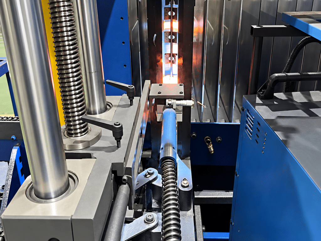
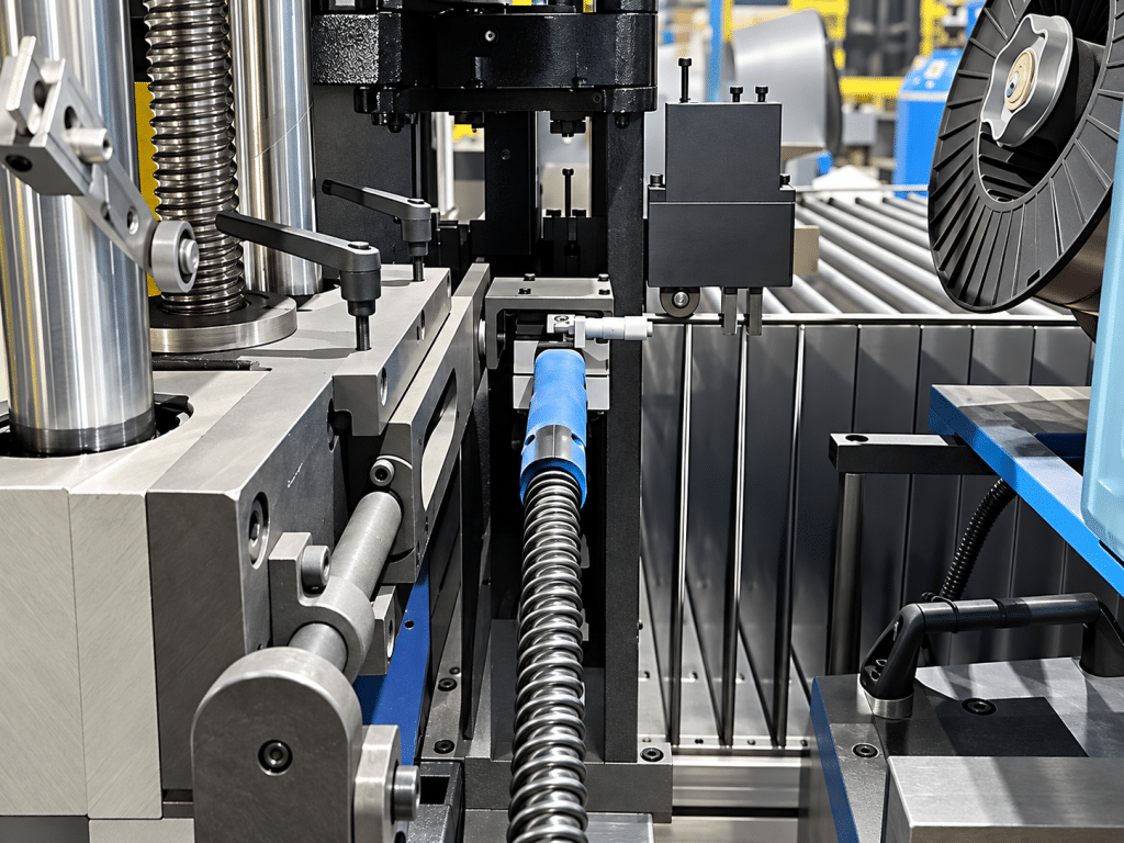
- Automatic round-bar welding. The round-bar stiffener is positioned by mechanism and welded along the crest automatically, removing the manual support operation and eliminating the 1–2 mm alignment error at its source.
- Wide specification coverage. Corrugated fin width 300–1600 mm, height 50–400 mm, minimum pitch ≥ 45 mm and weldable material thickness 1.0–1.5 mm cover the customer’s full range of main specifications.
The electrical and gas circuits use established common components. The customer’s maintenance team had worked with comparable welding sources before, and the commonality of consumables and torches helped them take ownership quickly.
4. Implementation and Commissioning
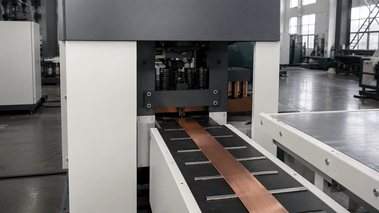
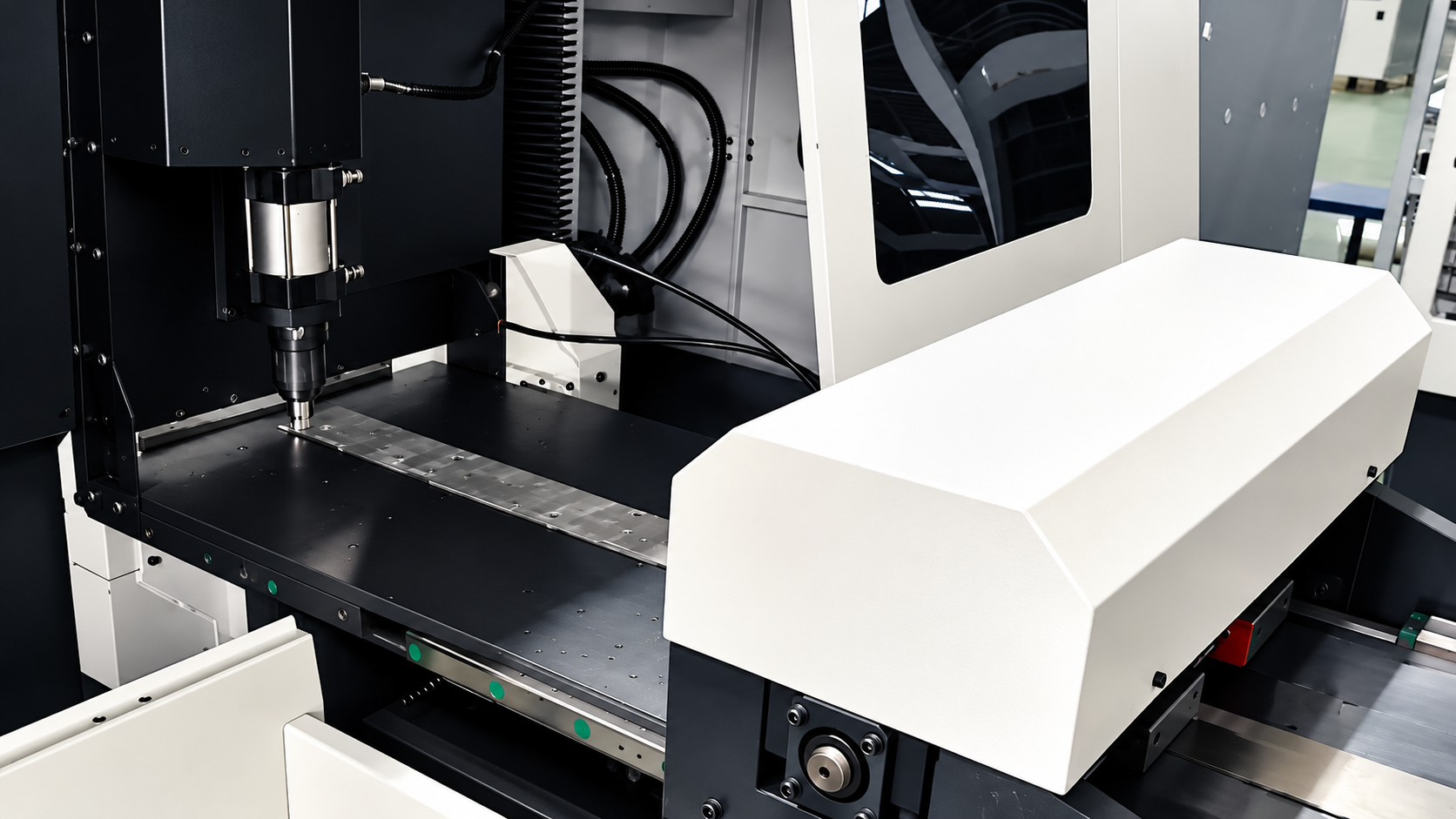
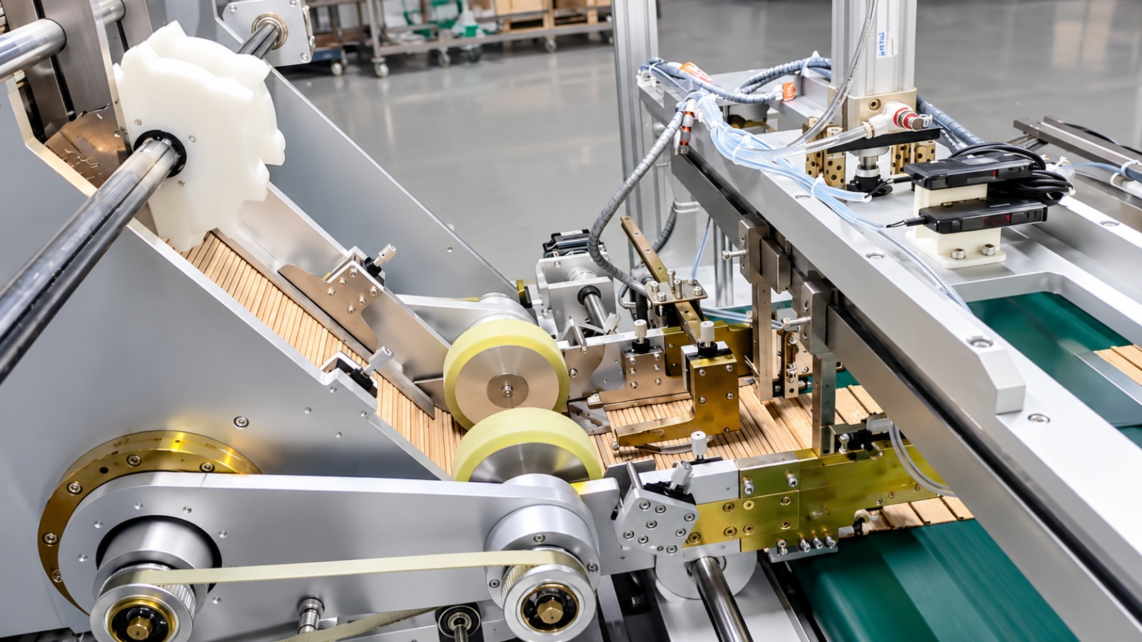
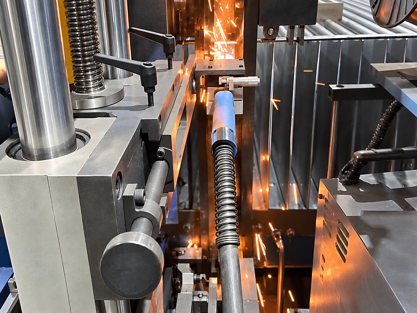
After the machine arrived by sea at the Cairo plant, TRANFOVIA engineers worked with the customer’s equipment and process teams through a three-step on-site commissioning. First, we checked the power supply (380 V three-phase), the shielding-gas circuit (85% Ar + 15% CO₂) and the torch cooling water, then ran each station empty. Second, with the customer’s main specification we threaded material through and tuned welding current, voltage, wire-feed speed and travel speed until bead appearance was qualified, penetration was stable and the cycle matched the forming main unit. Third, we ran trial welding across the customer’s full specification list and trained the operators to recall and switch weld procedures on the touch screen, handing over English operation and maintenance manuals at the same time. The photographs in this article show that commissioning — the round bar lands on the crest and the torch runs a continuous seam.
5. Acceptance Results
The welding machine was verified item by item against the technical agreement during commissioning. Key indicators (design and acceptance reference values; actual figures depend on the configuration):
| Indicator | Value / Result |
| Corrugated fin width | 300–1600 mm |
| Corrugated fin height | 50–400 mm |
| Minimum corrugation pitch | ≥ 45 mm |
| Weldable material thickness | 1.0–1.5 mm |
| Welding speed | 0.5–1.5 m/min (stepless) |
| Maximum welding current | 350 A |
| Wire diameter | 1.0 mm |
| Shielding gas | 85% Ar + 15% CO₂ |
Three changes were immediately visible to the customer: welding moved from “welder’s hand feel” to “parameters”, round-bar placement moved from “manually supported” to “mechanically positioned”, and bead appearance moved from a 60%–80% swing across the day to a consistency set by one stored procedure. The station that previously required certified welders is now run by two trained operators, which releases the senior welders to the tank-shell joints where their skill matters most.
6. Customer Feedback
“The most direct change is how steady the welds are — the same parameters give us a bead that looks the same on every fin. We used to need two senior hands watching this station; now two ordinary operators can keep it running.” — Customer Production Manager (at acceptance)
7. Summary and Next Steps
For corrugated tank manufacturers, competition at the welding operation has shifted from whether a weld can be made to whether it can be made identically every time. This machine integrates the gas-shielded welding source, automatic wire feeding and round-bar feeding into one unit, replacing an unrepeatable hand feel with a storable procedure — a practical answer to the welder shortage facing corrugated fin shops.
The customer is now evaluating combining this welding machine with the existing forming main unit and spot-welding equipment into a complete corrugated fin line. To configure a welding station around your fin specification, weld requirement and cycle target, contact the TRANFOVIA technical team for a proposal.
- WhatsApp: +86-15958243831
- Email: sales@tranfovia.com
- Website: https://tranfovia.com/