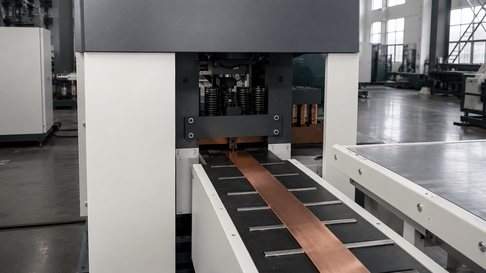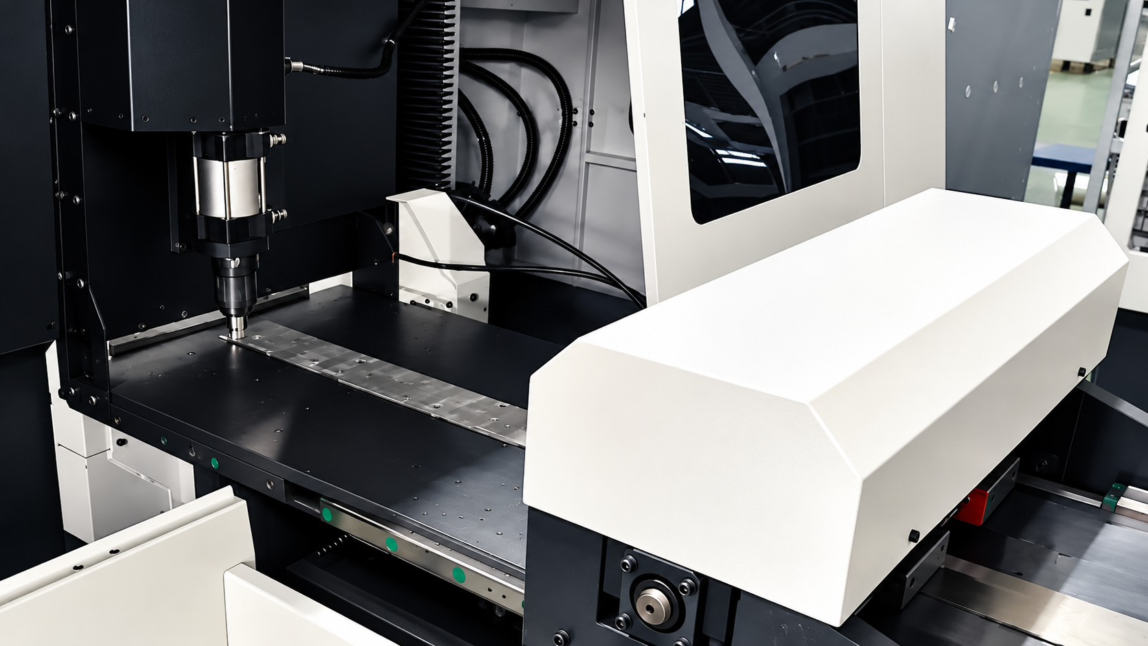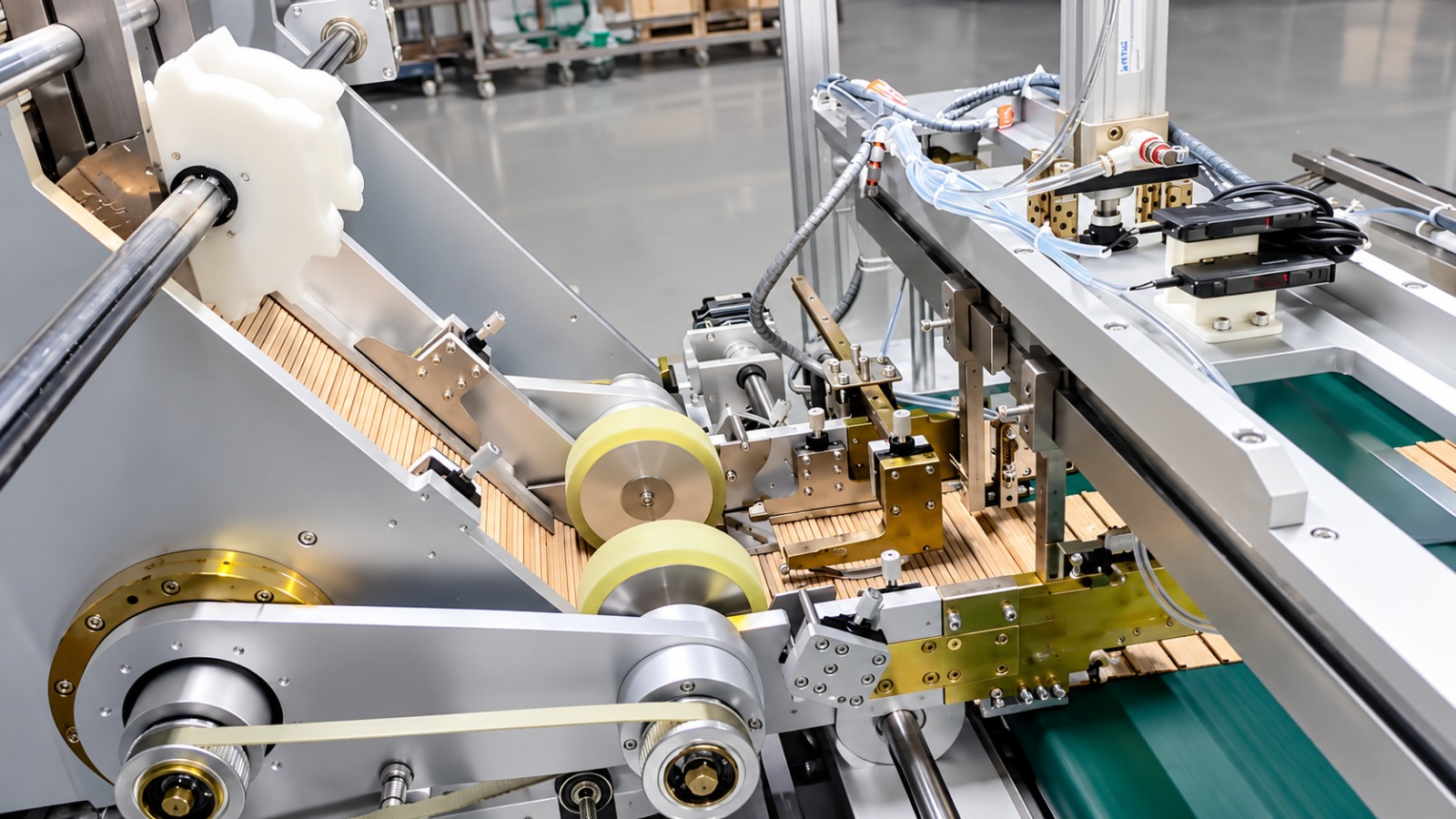
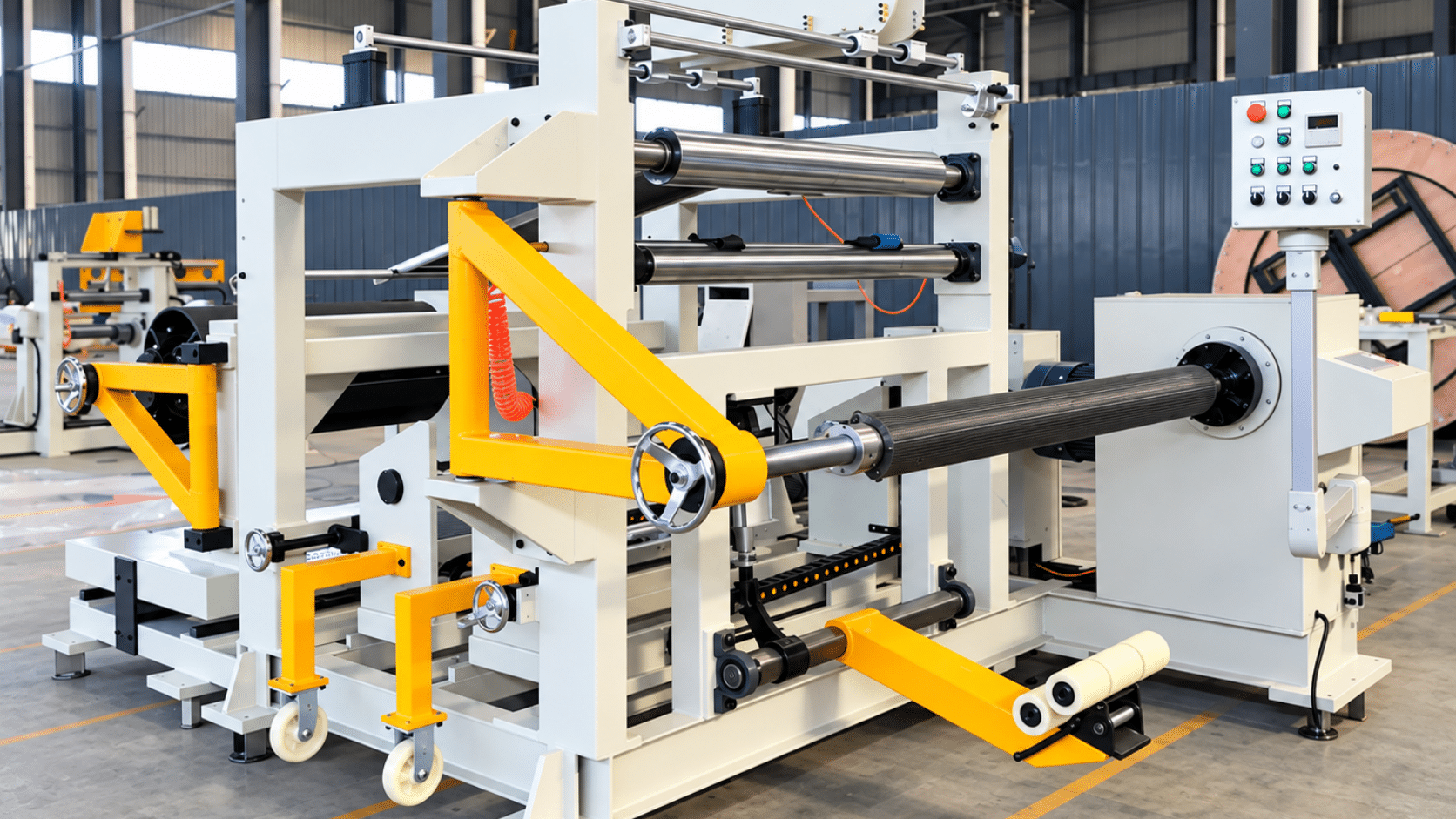
| Equipment | Single Layer Foil Winding Machine (DHR-4) |
| Customer | A transformer manufacturer in Lima, Peru (serving Andean markets) |
| Application | Foil coil winding for dry-type transformers, oil-immersed transformers and reactors, in copper or aluminium foil |
Customer information has been anonymized; only region and industry attributes are retained. Performance figures are acceptance and typical-condition reference values and may vary depending on line configuration.
1. Customer Background
This customer is based in Lima, Peru, and supplies dry-type transformers, oil-immersed distribution transformers and reactors to mining, municipal distribution and data-center projects. Its product range sits mainly between 500 kVA and 5 MVA. As mining and infrastructure investment picked up again in Peru, demand rose sharply for low-voltage, high-current foil coils — the low-voltage windings of dry-type transformers, earthing transformers and reactor windings are all wound from copper or aluminium foil into a cylinder. Until recently, the customer wound those foil coils on an ordinary horizontal winding machine: an operator guided the foil edge by hand and laid the layer insulation manually. As the order book filled, capacity and consistency came under pressure at the same time. After comparing proposals from several suppliers, the customer selected the DHR-4 single layer foil winding machine.
2. Industry Pain Points
A foil coil sounds simple in construction — one layer of conductor foil, one layer of insulation paper, wound into a cylinder. But precisely because there are so few layers, any drift shows up immediately at the coil ends: uneven ends, layer insulation that will not seat, and axial height out of tolerance. The customer’s previous process suffered from five recurring problems:
Foil drift corrected by hand. There was no correcting device after the uncoiler, so an operator held the foil edge in place while winding. The copper foil crept slowly along the axis, and by the last few turns the ends were visibly ragged.
Layer insulation laid out of line. Insulation paper was positioned by hand, and its edge did not always match the foil edge. The result was exposed foil or creases between layers — exactly the place where a withstand test fails.
Welding speed and quality set by the welder. Foil joints and terminal lead welding were done by hand with an argon arc torch. Travel speed and penetration depended entirely on the welder’s feel, so weld appearance and strength were not consistent across a batch of coils.
Every specification change meant re-aligning. Changing foil width or thickness meant re-centring the whole foil path, running trial turns and trimming — a stop measured in hours. With a growing number of small-batch, mixed-specification orders, the schedule was interrupted again and again.
Skill that could not be written down. The experienced operator knew that the foil should run “a little slack, with a light hand”, but that sentence does not translate into a work instruction. New hires took a long time to reach standard, so staff turnover fed straight through to delivery performance.
3. Solution
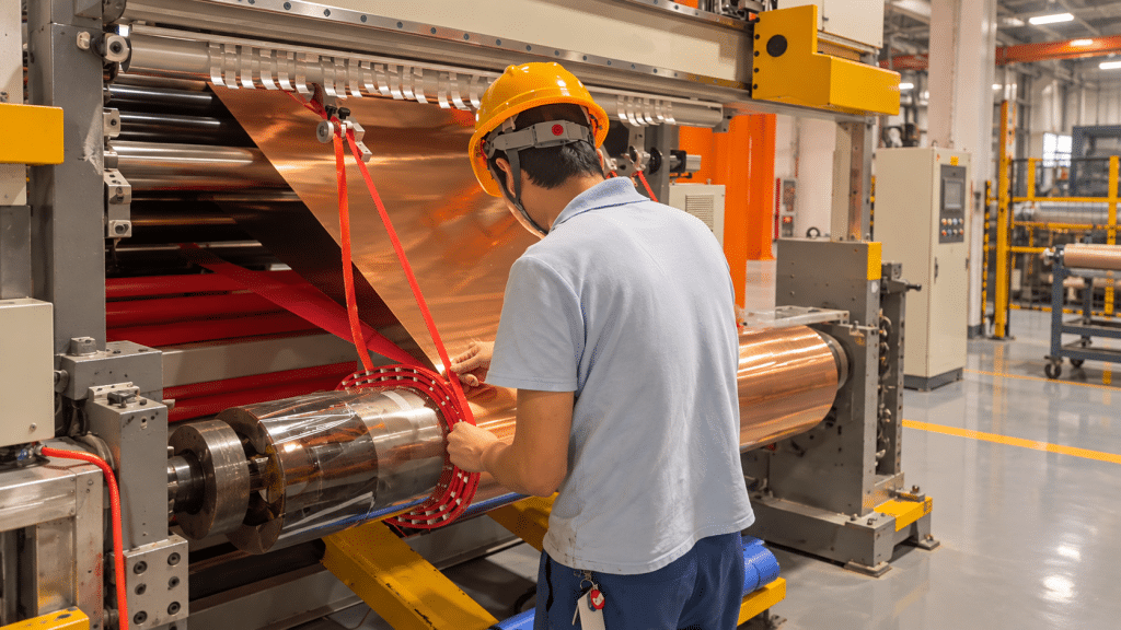
We configured the DHR-4 single layer foil winding machine for this customer, with one principle: move foil winding from craft to parameter.
- Correction over the whole path. Foil correction accuracy is ≤±0.5 mm, so the foil does not drift from pay-off through to the winding point. End neatness is guaranteed by the machine rather than by an operator’s hand.
- Coverage across the specification range. Copper foil from 0.35 to 2.2 mm and aluminium foil from 0.35 to 2.6 mm can be wound in single layer, with coil outside diameter up to 1000 mm and axial height up to 1600 mm, and two insulation layers — covering every foil winding the customer runs on dry-type transformers and reactors.
- Speed set to the material. Winding speed is continuously variable from 0 to 30 rpm, so thin foil can be wound slowly and thick foil quickly, each within a stable window. Main motor power is 15 kW and total installed power is 35 kW.
- Welding and cutting at the same station. Welding speed is 0–0.7 m/min, with a WSME-500 argon arc welder and a hydraulic coil cutter supplied as part of the unit. Foil joints, terminal lead welding and cut-to-length all happen at the winding station instead of waiting on a welder from another shop.
- Delivered as a complete set. Alongside the winding machine body, the delivery includes the welding frame and main unit, the uncoiler and the layer insulating trolley (all DHR-4), plus a square shaft with fixture at 60×60×1880, two foil shelf connectors, a foil shelf wrench, four hexagon keys and two vise grip pliers. The cooling water tank pump is built in.
The machine measures 6000×5200×2000 mm. Installation can be completed within four hours, after which the machine is ready to run, and training is provided for two winding operators at handover.
4. Implementation and Commissioning
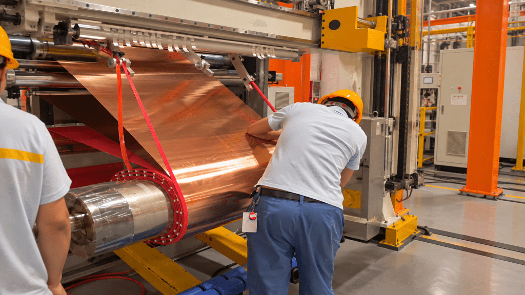
After the machine arrived by sea at the Lima plant, TRANFOVIA engineers worked with the customer’s equipment and process teams through a three-step on-site commissioning. First we verified the foundation, the power supply and the compressed air, connected the built-in cooling water tank and ran each station empty. Second, using the customer’s main specification, we threaded the foil through and tuned pay-off tension, correction response, winding speed and welding parameters until end neatness, layer insulation alignment and cycle time were stable together. Third, we ran trial windings across the customer’s specification list in both copper and aluminium foil, and trained the two operators on specification changeover and routine maintenance, handing over English operation and maintenance manuals at the same time.
5. Acceptance Results
The foil winding machine was verified item by item against the technical agreement. Key indicators (design and acceptance reference values; actual figures depend on the configuration):
| Indicator | Value / Result |
| Coil outside diameter | ≤ 1000 mm |
| Coil axial height | ≤ 1600 mm |
| Conductor material | Copper foil / aluminium foil |
| Conductor thickness (single layer) | Copper foil 0.35–2.2 mm; aluminium foil 0.35–2.6 mm |
| Number of insulation layers | 2 |
| Winding speed | 0–30 rpm, continuously variable |
| Correction accuracy | Foil ≤±0.5 mm |
| Welding speed | 0–0.7 m/min |
| Main motor / total power | 15 kW / 35 kW |
For the customer, the most visible changes are that foil alignment has moved from “held by hand” to “corrected by the machine”, that a specification change has moved from “stop and re-centre” to “switch parameters”, and that welding has moved from “waiting for a welder” into the winding station itself.
6. Customer Feedback
“Winding foil used to take two people holding it in place, and we still had to dress the ends afterwards. Now the foil tracks straight on its own, the ends come out right the first time, and we no longer wait for a welder.” — Customer Winding Shop Supervisor (at acceptance)
7. Summary and Next Steps
For manufacturers of dry-type transformers and reactors, competition in foil coils is no longer about whether a coil can be wound, but about end neatness, reliability of the interlayer insulation and changeover speed. This single layer foil winding machine replaces hand alignment with mechanical correction and brings welding and cutting into the same station — the direct path from operator experience to parameter-driven work.
To configure foil winding equipment around your foil widths and thicknesses, coil dimensions and output targets, contact the TRANFOVIA technical team for a proposal.
- WhatsApp: +86-15958243831
- Email: sales@tranfovia.com
- Website: https://tranfovia.com/