| Equipment | Transformer Corrugated Fin Production Line |
| Customer | A transformer corrugated tank manufacturer in Gujarat, India (serving the South Asian and Middle East markets) |
| Application | Fully automatic production of corrugated fins for oil-immersed transformer tanks — from coil loading and corrugation forming through to seam welding and reinforcing-rib spot welding |
Customer information has been anonymized; only region and industry attributes are retained. Performance figures are acceptance and typical-condition reference values and may vary depending on line configuration.
1. Customer Background
This customer, based in Gujarat, India, is a dedicated manufacturer of transformer corrugated tanks, supplying corrugated tank walls and corrugated fin assemblies to power and distribution transformer plants across South Asia and the Middle East. As grid investment in India expanded in step with transformer output, the customer’s corrugated fin orders moved away from few-spec, large-batch work toward high-mix production with frequently changing corrugation heights and fin widths — and the existing layout of stand-alone machines plus manual handling could no longer keep up. After comparing several suppliers, the customer chose our corrugated fin production line. This installation also forms part of our transformer tank equipment export record: identical lines have been delivered to customers in India, Thailand, Indonesia and Sudan.
2. Industry Pain Points
A corrugated fin is the primary heat-dissipating surface of an oil-immersed transformer tank. It starts as thin steel sheet, is folded and pressed into corrugations, then reinforced with welded round bars or ribs before the finished fin is welded onto the tank wall. Simple as it looks, it decides two things at once: how well the transformer dissipates heat, and whether the tank stays leak-tight. The customer’s manual line produced five recurring problems:
Forming dimensions set by hand. Folding relied on manual work with simple tooling, so corrugation height and pitch fluctuated. Fins would not line up when welded into groups, forcing repeated rework.
Weld quality that depended on the welder. Seam welding and reinforcing-rib spot welding were both done by hand. Porosity and incomplete fusion appeared from time to time, and a single leak meant reworking an entire transformer.
Output that could not scale. Manual work produced only a few fins per minute, so delivery dates slipped whenever orders piled up.
Slow changeovers. Switching corrugation height or fin width required re-setting the tooling, with long stops that made high-mix orders hard to schedule.
A shortage of welders. Skilled welders were increasingly hard to recruit, and both labor cost and hiring pressure rose year on year.
3. Solution
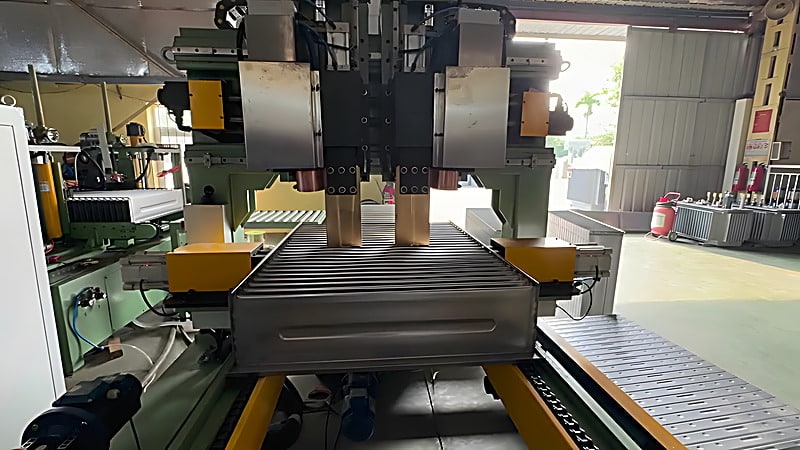
We configured a complete line from coil loading to spot welding: automatic decoiler → corrugated fin forming machine (main unit) → automatic corrugated fin welding machine → reinforcing-rib spot welder → conveyors, supported by hydraulic, electrical and industrial oil-cooling systems. The design principle was to move corrugated fin manufacturing from skill-based work to program-based work:
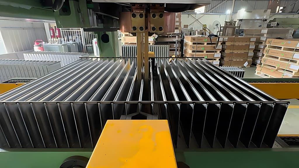
- One-touch forming. The operator enters corrugation height, pitch and quantity on the Siemens touch screen, and the forming machine automatically folds and presses the entire corrugated fin in a continuous run. Corrugation height is freely set from 50 to 400 mm, at a forming speed of 3–4 fins per minute.
- One machine, multiple specifications. Sheet width 300–1600 mm, corrugation height 50–400 mm and sheet thickness 1.0–1.5 mm are all handled on one machine, covering everything from small to large transformer tanks. Oil-channel gaps of 4 mm or 6 mm are available to suit different heat-dissipation areas.
- Integrated rib embossment. The forming process can press one or two reinforcing-rib embossments at the same time — one rib at a corrugation height of 150 mm or more, two ribs at 250 mm or more — markedly improving fin stiffness and cooling performance.
- Welding by parameters. The automatic welding machine uses a Japanese OTC DM350 digital MAG welder with a maximum welding current of 350 A and stepless welding speed from 0.5 to 1.5 m/min. Shielding with a 85% Ar + 15% CO₂ mixture produces dense, porosity-free welds, and round-bar reinforcements can be positioned and welded automatically.
- Spot welding by servo. The reinforcing-rib spot welder combines dual 50 KVA welding power supplies with a servo positioning system, laying out spot spacing and row pitch automatically. Spot nuggets are full and distortion is minimal, while water cooling keeps the electrodes working continuously without overheating.
- Stable decoiling. The automatic decoiler carries steel coils up to 7 tonnes; its hydraulic expanding mandrel grips firmly and releases smoothly without damaging the coil’s inner wraps, and it is interlocked with the forming machine’s PLC for automatic speed matching.
Core components include Siemens PLC and touch screen, Huade hydraulics, Schneider electrics, Beijing Shidai servo motors and AirTAC pneumatic components, giving the line stable, reliable operation.
4. Implementation and Commissioning
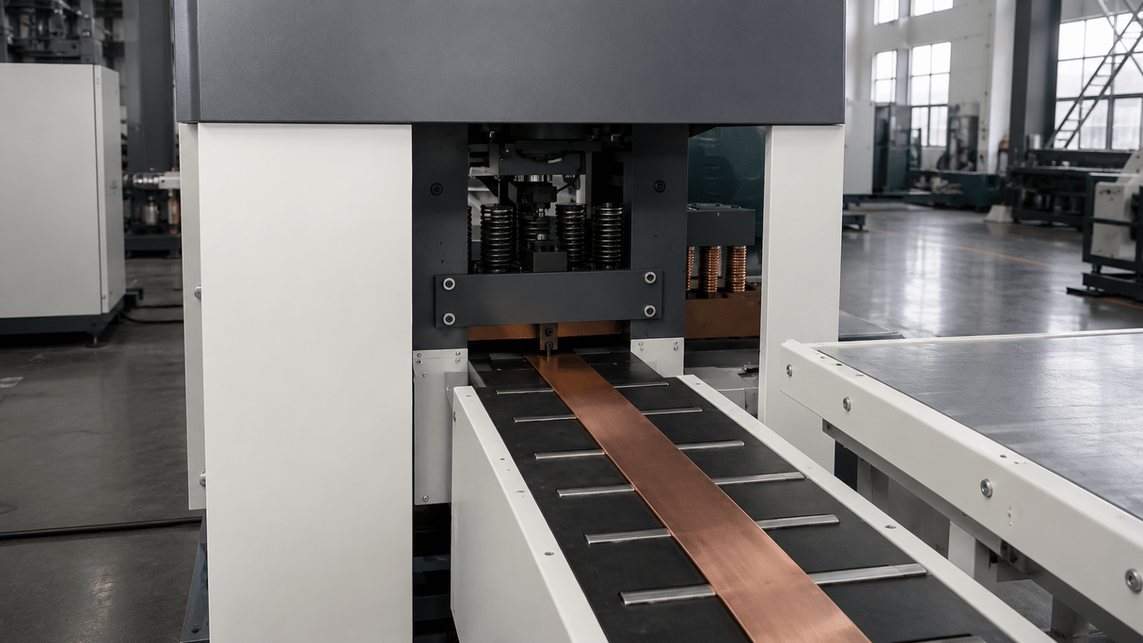
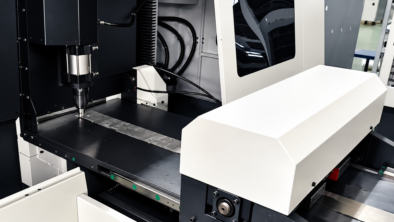
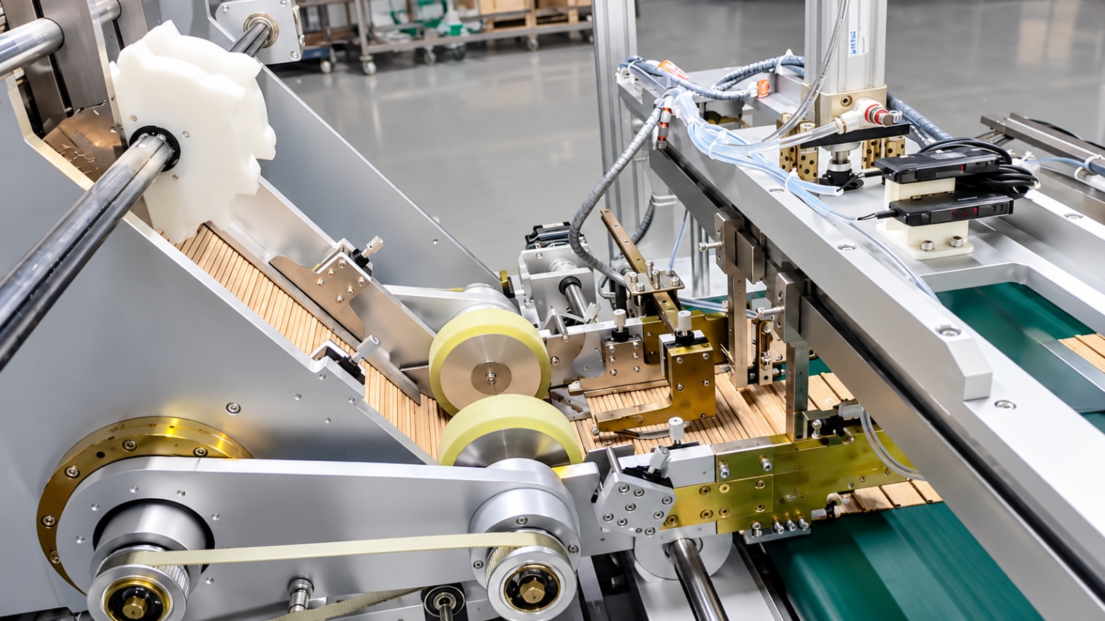
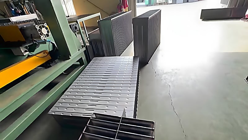
After the line arrived by sea, TRANFOVIA engineers worked with the customer’s equipment and process teams through a three-step on-site commissioning. First, we verified the foundations, the total power supply (380 V three-phase) and the welders’ cooling-water and shielding-gas circuits, then ran each machine empty. Second, with the customer’s main specification we threaded material through the whole line, tuned forming, seam welding and spot welding parameters station by station, and synchronized the line tempo. Third, we produced trial corrugated fins against the acceptance criteria of the technical agreement, and delivered English operation and maintenance manuals together with hands-on training for the customer’s operators and maintenance crew. The photographs in this article were taken during that commissioning — corrugated fins flow continuously from decoiling and forming through seam welding to reinforcing-rib spot welding, with no manual handling in between.
5. Acceptance Results
The line was verified item by item against the technical agreement during commissioning. Key indicators (design and acceptance reference values; actual figures depend on the configured line):
| Indicator | Value / Result |
| Corrugated fin width | 300–1600 mm |
| Corrugated fin height | 50–400 mm |
| Minimum corrugation pitch | ≥ 45 mm |
| Material thickness | 1.0–1.5 mm |
| Forming speed | 3–4 fins per minute |
| Welding speed | 0.5–1.5 m/min (stepless) |
| Oil-channel gap | 4 mm / 6 mm |
| Operators for the whole line | 1–2 people |
The two most visible changes for the customer: corrugated fins now travel from steel coil to finished part in one pass, with no manual folding or handling in between; and a spec changeover went from “re-setting the tooling” to “entering parameters on the touch screen”, so high-mix orders can be scheduled on the same line.
6. Customer Feedback
“Once the line was running, the most obvious change was weld consistency — the same parameters now give us fins that are all very much alike. After training, our own operators can already handle spec changeovers and daily checks on their own.” — Customer Production Manager (at acceptance)
7. Summary and Next Steps
For transformer tank manufacturers, competition in corrugated fins is no longer about whether a fin can be made, but about forming accuracy, weld pass rates and speed across mixed specifications. This production line integrates decoiling, forming, seam welding and spot welding into one continuous flow, replacing manual skill with programmed parameters — the direct path from stand-alone machines to a true corrugated fin line.
To configure a complete line around your corrugation-height range, fin widths and output targets, contact the TRANFOVIA technical team for a proposal.
- WhatsApp: +86-15958243831
- Email: sales@tranfovia.com
- Website: https://tranfovia.com/