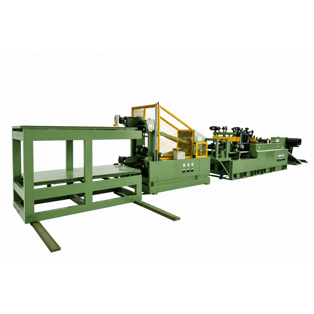
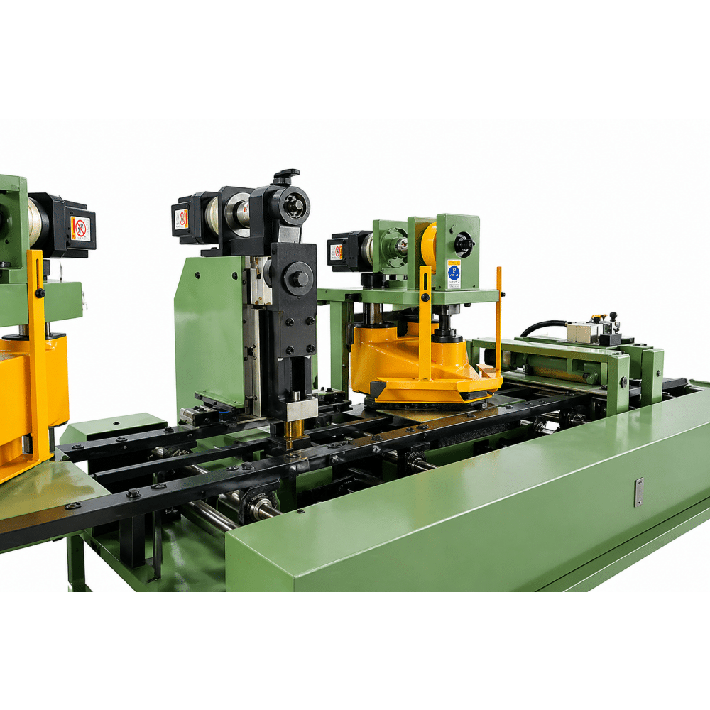
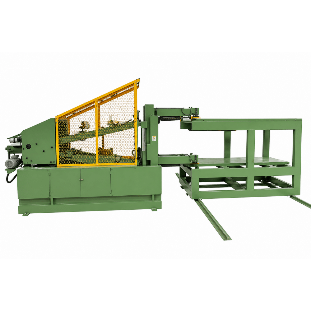
The TRANFOVIA Center-Position Transformer Core Cutting Line is designed for transformer manufacturers that require the silicon steel strip to remain referenced around the line center during lamination processing. The listed series covers 0.18-0.35 mm silicon steel, cutting widths up to 600 mm and feeding speeds up to 240 m/min.
The line cuts silicon steel strip into programmed transformer core laminations while maintaining a centered material path through the punching, notching and cutting sequence. It is suited to factories whose core design and manufacturing method specify center-position processing, including production plans with step-lap or related lamination geometries.
| Model | Cutting Thickness | Cutting Width | Cut Length | Feeding Speed | Cutting Burr | Cutting Length Accuracy | Cutting Angle Accuracy | Total Motor Power |
| XE-LL-300ZX | 0.18-0.35 mm | 40-300 mm | 350-2000 mm | 240 m/min | ≤0.02 mm | ±0.1 mm | ±0.025° | 22 kW |
| XE-LL-400ZX | 0.18-0.35 mm | 40-400 mm | 350-2500 mm | 240 m/min | ≤0.02 mm | ±0.1 mm | ±0.025° | 23 kW |
| XE-LL-600ZX | 0.18-0.35 mm | 60-600 mm | 500-3500 mm | 240 m/min | ≤0.02 mm | ±0.1 mm | ±0.025° | 34 kW |
| Selection Point | Center-Position Line | Side-Position Line |
| Material reference | Material path is centered through the cutting process | Material is processed with a side-position reference |
| Listed thickness range | 0.18-0.35 mm | 0.23-0.35 mm |
| Listed feed speed | 240 m/min | 180 m/min |
| Best fit | Factories specifying center-position processing and 300/400/600 mm classes | Factories whose approved lamination process is based on side positioning |
The listed range is 0.18-0.35 mm.
The XE-LL-600ZX reaches 600 mm cutting width.
The XE-LL-600ZX reaches 3500 mm cutting length.
The standard 300, 400 and 600 class models are listed at 240 m/min.
The listed values are burr ≤0.02 mm, cutting-length accuracy ±0.1 mm and cutting-angle accuracy ±0.025°.
The difference is the material-reference method through the cutting process. The center-position line keeps the strip path referenced around the centerline, while the side-position line uses a side reference.
Choose according to the maximum lamination width and length. The 300 class covers up to 300 mm width and 2000 mm length, the 400 class up to 400 mm and 2500 mm, and the 600 class up to 600 mm and 3500 mm.
Provide transformer core lamination drawings, silicon steel grade and thickness, strip width, cut-length range, punching/notching requirements, step-lap sequence, collection method and plant electrical standard.