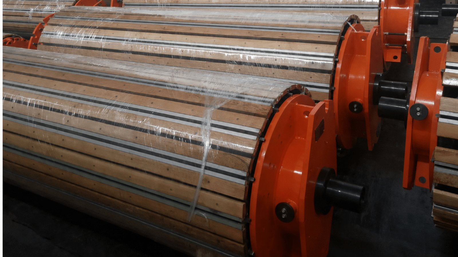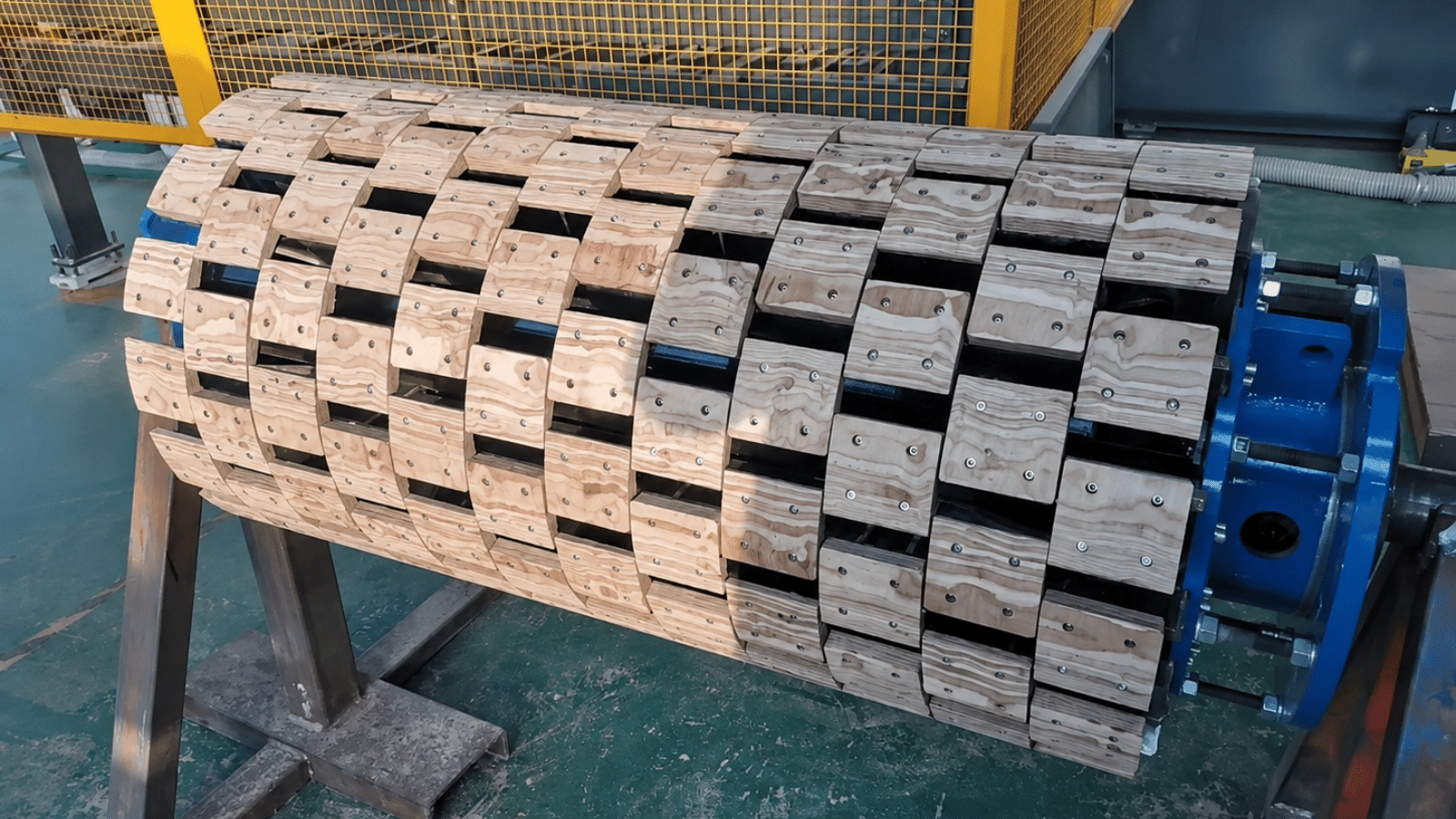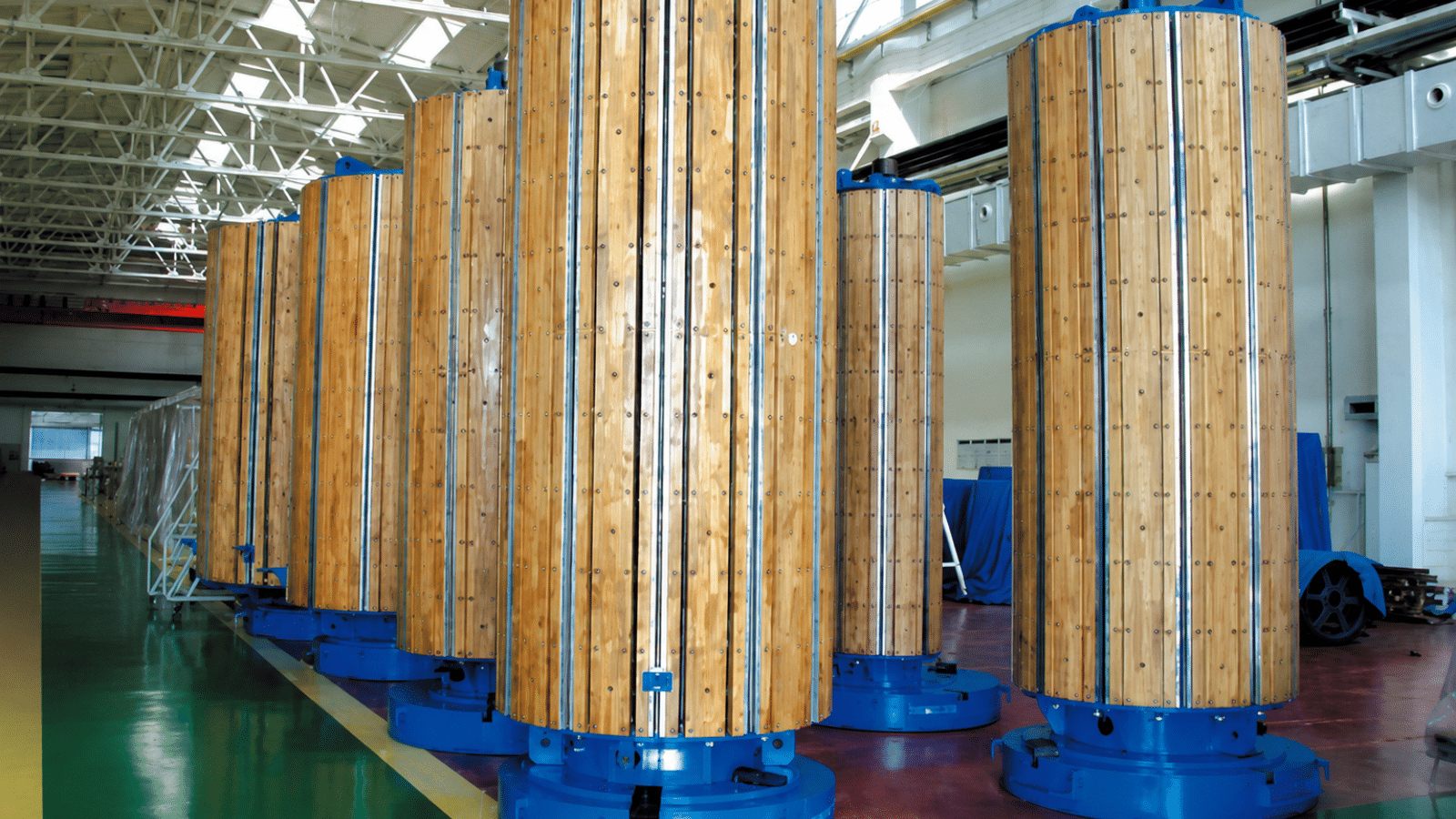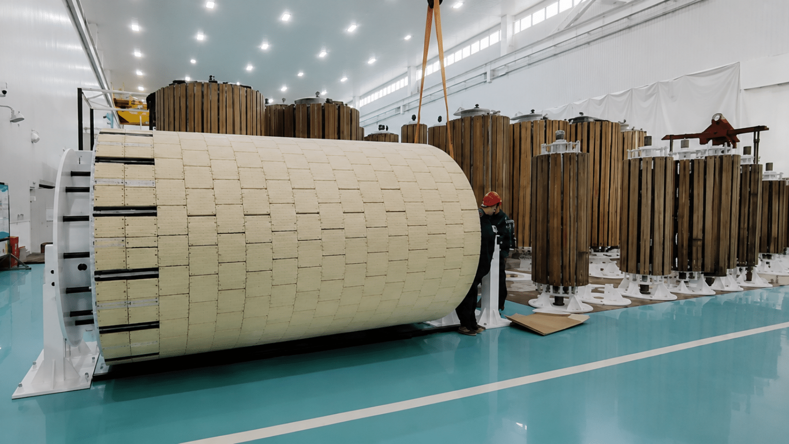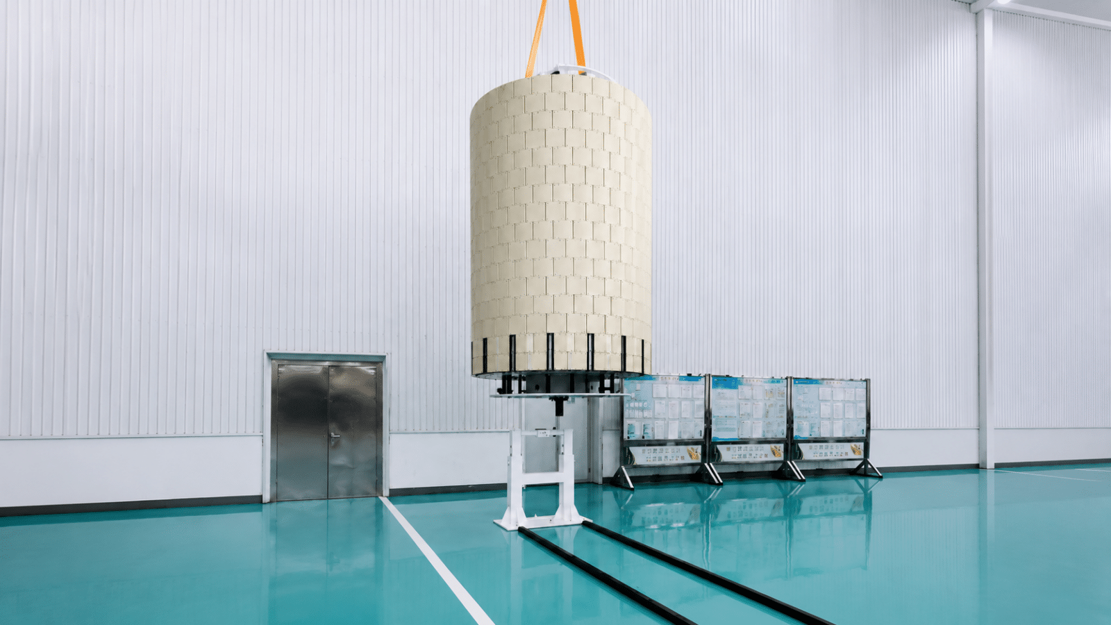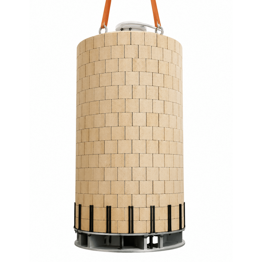
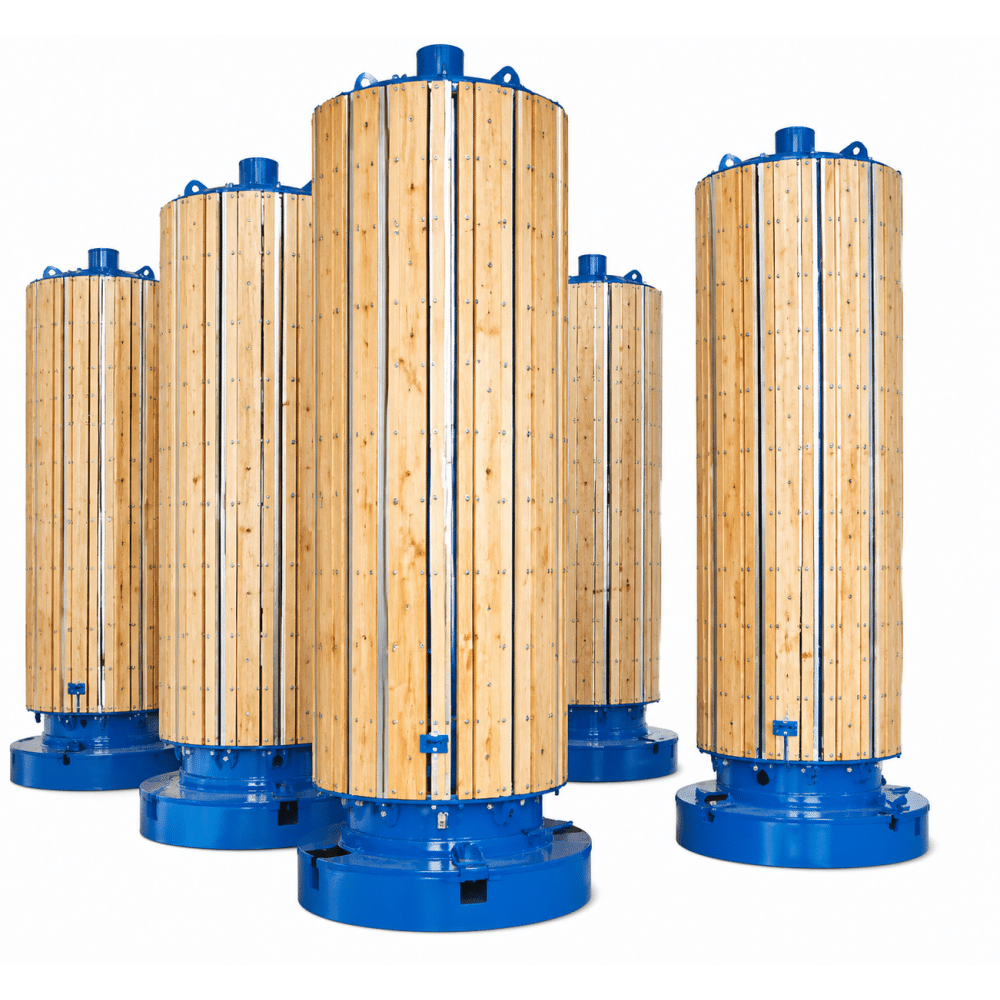
The TRANFOVIA expandable winding mandrel supports transformer coil winding across a wide range of inner diameters and coil weights. Its reducer-driven expansion mechanism holds the required diameter during winding, then contracts for controlled coil removal without forcing or distorting the finished winding.
A fixed winding form must match one coil diameter, and removing a tightly wound coil can require significant lifting force or additional handling. An expandable mandrel changes the process: the mandrel is expanded to the specified winding diameter, supports the conductor and insulation during production, and is reduced after winding so the coil can be removed with less mechanical interference.
This makes the mandrel especially useful for transformer factories producing multiple coil sizes or heavy coils that require stable support throughout winding. Twelve standard capacity ranges cover nominal diameters from 180 to 3000 mm and loads from 1 to 20 tons.
| Stage | Mandrel Action | Process Result |
| 1 | Set the required diameter | The reducer-driven transmission moves the sliding sleeve and support rods to position the battens at the required winding diameter. |
| 2 | Lock the working geometry | The cage, battens and right-angle limiter maintain the cylindrical winding surface during production. |
| 3 | Wind the transformer coil | The mandrel carries the coil load while the winding machine rotates the assembly under the specified process conditions. |
| 4 | Release the expanded structure | After winding, the transmission retracts the support structure and reduces the effective diameter. |
| 5 | Remove the finished coil | The reduced mandrel diameter creates clearance between the coil and winding form, helping prevent damage during unloading. |
The winding mandrel determines the initial inner geometry of the transformer coil. Excessive diameter variation can affect the coil’s roundness, insulation fit, support blocks and subsequent assembly with the core or adjacent windings. The mandrel maintains diameter deviation below 1 mm between any two measured points and cylindricity below 1 mm, providing a controlled reference surface for winding.
| Configuration | Diameter Range (mm) | With Additional Battens (mm) | Load (t) | Batten Length (mm) | Adjustment |
| KTM-180 | 180-260 | 220-260 | 1.0 | 800-1300 | Reducer |
| KTM-260 | 260-390 | 325-390 | 1.5 | 1000-1800 | |
| KTM-340 | 340-640 | 490-640 | 2.0 | 1200-2000 | |
| KTM-450 | 450-750 | 600-750 | 2.0 | 1300-1800 | |
| KTM-500 | 500-900 | 700-900 | 3.0 | 1300-2300 | |
| KTM-540 | 540-930 | 730-930 | 3.0 | 1300-1800 | |
| KTM-600 | 600-900 | 750-900 | 5.0 | 1400-2200 | |
| KTM-700 | 700-1300 | 1000-1300 | 8.0 | 1600-3200 | |
| KTM-1100 | 1100-1500 | 1300-1500 | 8.0 | 2000-2300 | |
| KTM-1300 | 1300-1900 | 1600-1900 | 10 | 2200-3000 | |
| KTM-1900 | 1900-2520 | 2210-2520 | 16 | 3000-4000 | |
| KTM-2300 | 2300-3000 | 2640-3000 | 20 | 3000-4000 |
It provides an adjustable cylindrical support for transformer coil winding and contracts after winding to create clearance for coil removal.
The available configurations cover nominal winding diameters from 180 to 3000 mm.
The largest standard configuration supports a load of up to 20 tons. The correct selection depends on coil weight, mandrel length and winding-machine interface.
Additional support battens increase the effective winding diameter for the upper section of a configuration’s working range.
Diameter deviation between any two points is below 1 mm, and cylindricity is below 1 mm.
The standard configurations use reducer-driven adjustment to expand or contract the supporting battens.
No. Each configuration has a defined diameter, load and batten-length range. Several configurations may still be required for a factory with a very broad product mix.
Provide the coil inner diameter, axial length, total winding load, winding-machine interface and required removal clearance.