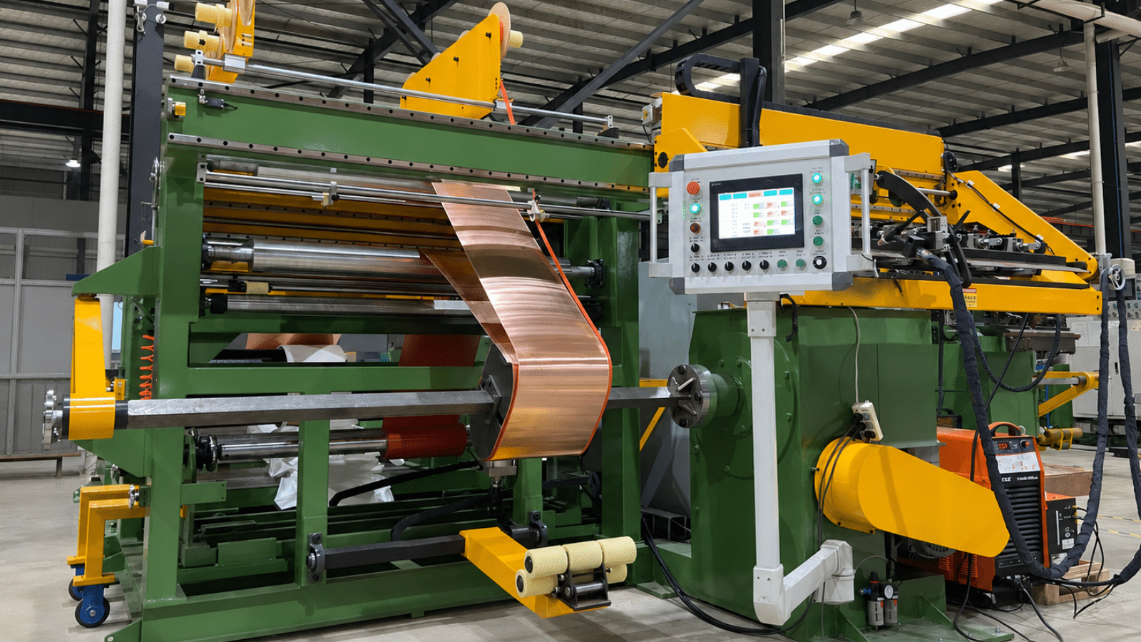
Double Layer Foil Winding Machine for LV Transformer Coils
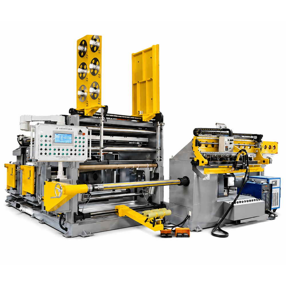
The TRANFOVIA Double Layer Foil Winding Machine is designed for low-voltage transformer coil drawings that require a specified double-foil conductor arrangement or a higher combined conductor thickness than a standard one-foil process can provide.
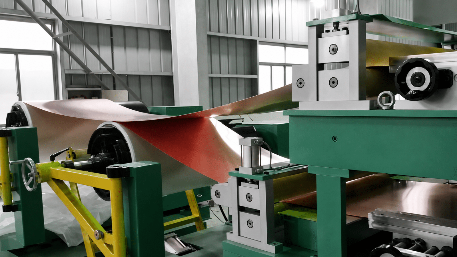
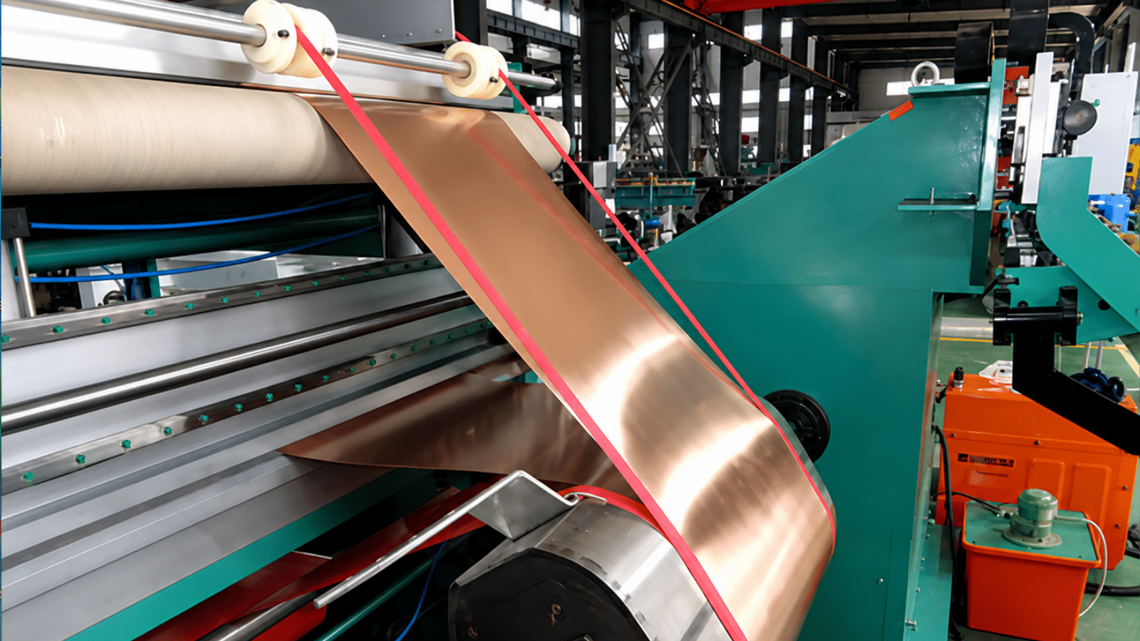
The equipment supports copper and aluminum foil, retains the listed single-layer ranges and extends the combined thickness to 0.7-4.4 mm for copper and 0.7-5.4 mm for aluminum in double-layer operation. It integrates foil unwinding, insulation feeding, deviation correction, winding, welding support and hydraulic cutting.
Applications
- Low-voltage transformer coils with a specified two-foil conductor arrangement.
- Copper foil designs requiring a combined thickness from 0.7 to 4.4 mm.
- Aluminum foil designs requiring a combined thickness from 0.7 to 5.4 mm.
- Dry-type transformer, oil-immersed transformer and reactor foil coils.
- Factories that need both the listed single-layer range and double-layer capability on one production platform.
Main Features
- Double-foil conductor capability. The main purchasing reason is the ability to process the specified two-foil configuration and higher combined conductor thickness.
- Single-layer production retained. The same platform also supports copper foil from 0.35-2.2 mm and aluminum foil from 0.35-2.6 mm in single-layer operation.
- Extended combined thickness range. Double-layer operation covers copper from 0.7-4.4 mm and aluminum from 0.7-5.4 mm.
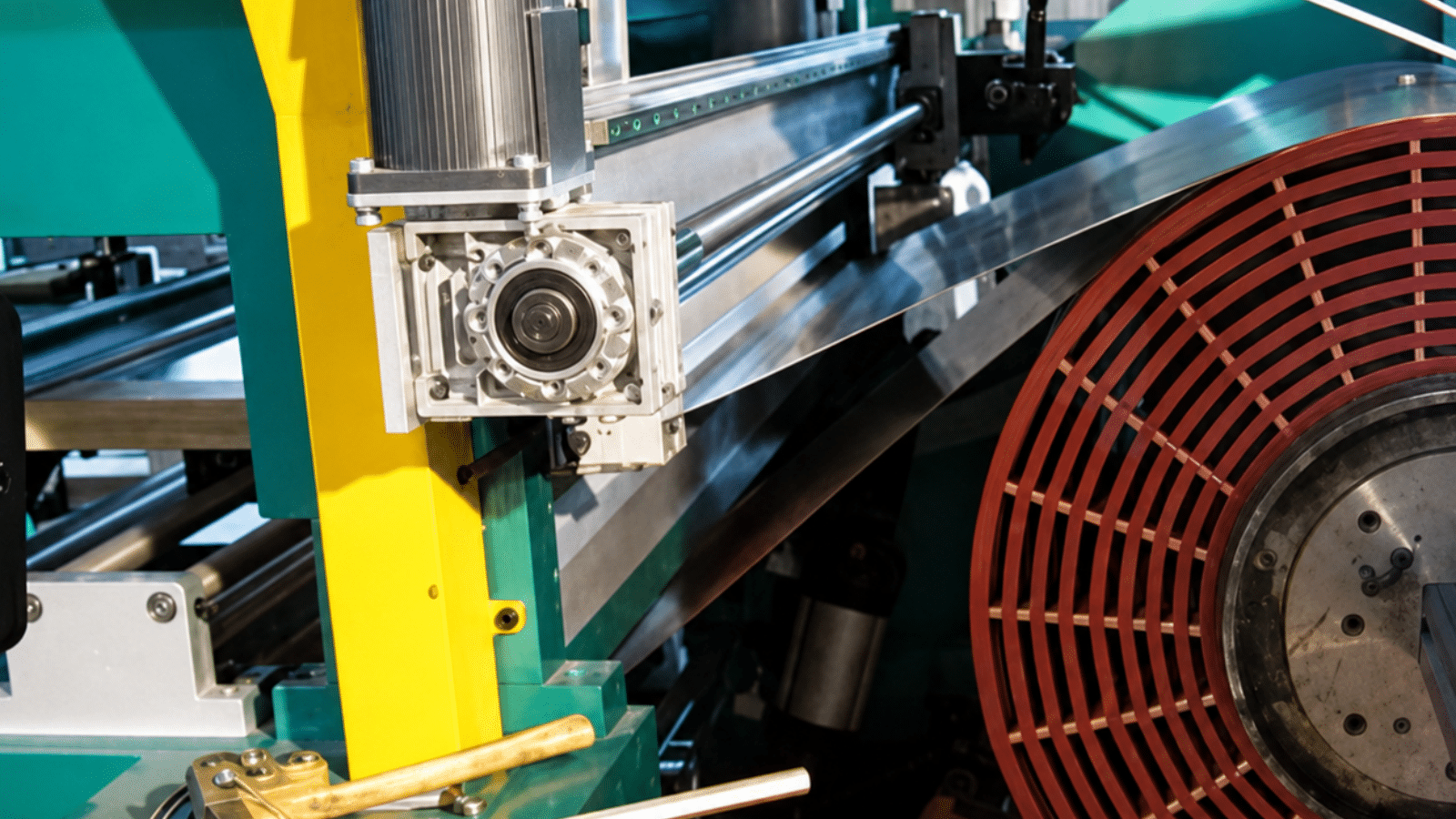
- Foil deviation correction. The correction system controls lateral foil position with a stated rectification accuracy of ≤ ±0.5 mm.
- Large LV coil envelope. The maximum stated coil outside diameter is 1,000 mm and the maximum axial height is 1,600 mm.
- Continuously adjustable winding speed. The 0-30 r/min range supports controlled setup, welding and production winding.
- Integrated process equipment. The standard scope includes foil unwinding, layer-insulation feeding, welding support, cooling-water equipment and hydraulic foil cutting.
- Project-level capacity planning. The listed 75 kW total installed power and 7,100 x 5,200 x 2,500 mm dimensions should be included in workshop utility and layout planning.
- Installation and operator training. The equipment information states approximately four hours for installation under prepared site conditions and training for two operators.
Foil Thickness Range for Double Layer Operation
Machine selection should follow the conductor arrangement shown on the approved coil drawing. The maximum double-layer values are combined thickness ranges, not a recommendation to use the highest value for every transformer design.
- Copper foil – single-layer range: 0.35-2.2 mm.
- Copper foil – double-layer combined range: 0.7-4.4 mm.
- Aluminum foil – single-layer range: 0.35-2.6 mm.
- Aluminum foil – double-layer combined range: 0.7-5.4 mm.
Technical Parameters
| Parameter |
Unit |
Specification |
| Maximum winding-coil outside diameter |
mm |
≤ 1,000 |
| Maximum coil axial height |
mm |
≤ 1,600 |
| Conducting material |
– |
Copper foil / aluminum foil |
| Copper foil – single layer |
mm |
0.35-2.2 |
| Copper foil – double layers |
mm |
0.7-4.4 combined |
| Aluminum foil – single layer |
mm |
0.35-2.6 |
| Aluminum foil – double layers |
mm |
0.7-5.4 combined |
| Number of insulation layers |
layer(s) |
2 |
| Winding speed |
r/min |
0-30, continuously adjustable |
| Rectification accuracy |
mm |
≤ ±0.5 |
| Welding speed |
m/min |
0-0.7 |
| Main motor power |
kW |
11 |
| Total installed power |
kW |
75 |
| Overall dimensions (L x W x H) |
mm |
7,100 x 5,200 x 2,500 |
Standard Configuration
- Main foil winding machine body and welding frame.
- Conductor uncoiling system and layer-insulation trolley.
- Hydraulic foil cutter.
- WSME-500 argon welder and cooling-water tank/pump system.
- Square shaft with fixture and foil-support accessories.
- Foil-support connectors, dedicated wrench and hand tools.
- Operating instructions and welding materials.
When Double-Foil Capability Is Required
Choose this machine when the approved coil design specifies two conductor foils, when the combined conductor thickness exceeds the one-foil range, or when one production line must cover both the listed single-layer and double-layer products.
Do not select the larger system only because it appears more capable. A one-foil machine remains the more focused choice when all products stay within the single-layer thickness range and the factory does not need double-foil processing.
FAQ
- What is a double layer foil winding machine?
It is a transformer coil winding machine configured for a specified two-foil conductor process while also retaining the stated single-layer foil ranges.
- What is the maximum copper foil thickness?
The listed copper range is 0.35-2.2 mm for single-layer operation and 0.7-4.4 mm combined for double-layer operation.
- What is the maximum aluminum foil thickness?
The listed aluminum range is 0.35-2.6 mm for single-layer operation and 0.7-5.4 mm combined for double-layer operation.
- Does the machine always have to run in double-layer mode?
No. The technical data also lists single-layer foil ranges. The operating configuration follows the approved coil design.
- What is the maximum coil size?
The stated maximum outside diameter is 1,000 mm and the maximum axial height is 1,600 mm.
- How is foil alignment controlled?
A deviation-correction system compensates for lateral foil movement with a stated rectification accuracy of ≤ ±0.5 mm.
- What should buyers confirm before ordering?
Confirm the layer arrangement, individual and combined foil thickness, roll dimensions and weight, insulation sequence, welding method, output target, utilities and acceptance requirements.